EVCO S.p.A. c-pro 3 nano | Hardware Manual ver. 1.0 | Code 114CP3NE104
page 11 of 26
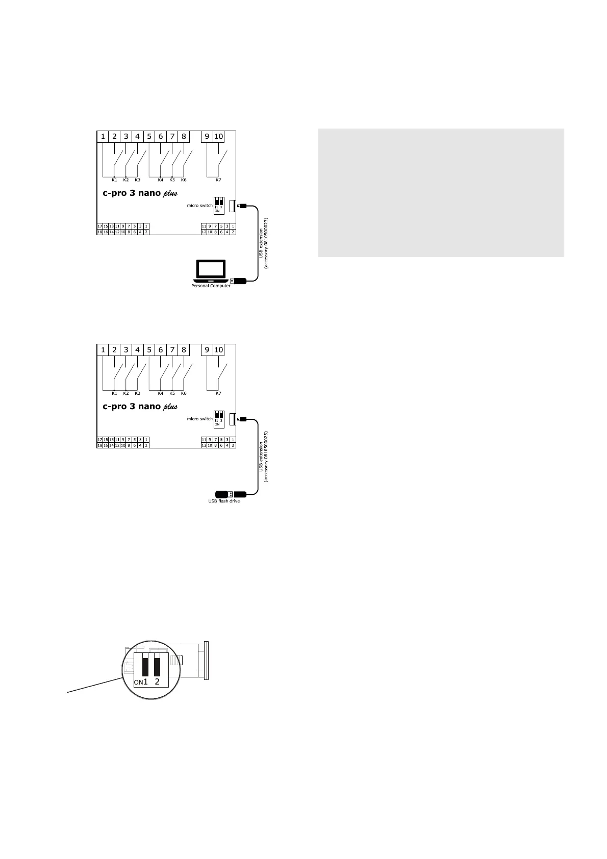
4.10 USB port connection to a personal
computer
The picture below shows the c-pro 3 nano plus USB port connection to a
personal computer.
4.11 USB flash drive connection
The picture below shows a USB flash drive connection to the c-pro 3 nano plus.
4.12 Fitting the termination resistor for
the RS-485 MODBUS and CAN
networks
To reduce any reflections on the signal transmitted along the cables connecting
the devices to a RS-485 MODBUS network and/or a CAN network it is
necessary to fit a termination resistor to the first and last device in the
network.
The picture below shows the left side of the devices.
To fit the RS-485 MODBUS network termination resistor, place micro-switch 1
in position ON. To fit the CAN network termination resistor, place micro-switch
2 in position ON.
4.13 Polarisation of RS-485 MODBUS
network
The RS-485 MODBUS network can be polarised using the UNI-PRO 3
development environment.
PRECAUTIONS FOR ELECTRICAL CONNECTION
- If using an electrical or pneumatic screwdriver, adjust the tightening
torque.
- If the device has been moved from a cold to a warm place, the humidity
may have caused condensation to form inside. Wait about an hour before
switching on the power.
- Make sure that the supply voltage, electrical frequency and power are
within the set limits. See the section TECHNICAL SPECIFICATIONS.
- Disconnect the power supply before doing any type of maintenance.
- Do not use the device as safety device.
- For repairs and for further information, contact the EVCO sales network.
 Loading...


