Evco S.r.l. • Code 104CPRN00A00
C-PRO NANO Programmable and application-oriented controllers version 1.00
GB ENGLISH
1 GETTING STARTED
1.1 Important
Read these instructions carefully before installing and using the instru-
ment and follow all additional information for installation and electrical
connection; keep these instructions close to the instrument for future
consultations.
The instrument must be disposed according to the local
legislation about the collection for electrical and electronic
equipment.
2 INTRODUCTION
2.1 Introduction
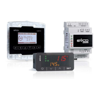
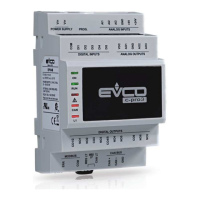
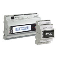
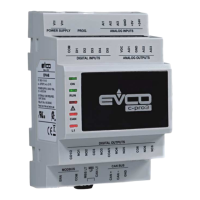
C-PRO NANO is a family of programmable or application-oriented con-
trollers.
The family is made of the following models:
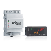
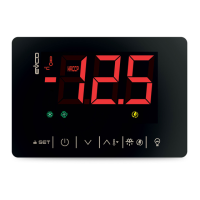
• CPN1D0* - built-in controller with display for applications in refrigera-
tion field (look at the following drawing).
• CPN1D1* - built-in controller with display for applications in condi-
tioning field (look at the following drawing)
The controllers have the following kind of inputs and outputs:
• 4 analog inputs
• 5 digital inputs
• 1 output for cut phase module EVDFAN1
• 2 analog outputs (by request)
• 6 digital outputs.
Through the expansions belonging to the family C-PRO EXP MICRO it is
possible to increase the I/O of the following kind of inputs and out-
puts:
• 4 analog inputs
• 5 digital inputs
• 6 digital outputs.
The programmable versions can be programmed with the develop-
ment ambient UNI-PRO.
For further information consult the Hardware manual of C-PRO NANO,
the Software manual of UNI-PRO and the Application manual.
3 SIZE AND INSTALLATION
3.1 Size
Size in mm (in).
DIMENS. MINIMUM TYPICAL MAXIMUM
A 71.0 (2.795) 71.0 (2.795) 71.8 (2.826)
B 29.0 (1.141) 29.0 (1.141) 29.8 (1.173)
3.2 Installation
Panel mounting, with click brackets (supplied by the builder).
3.3 Additional information for installation
• the panel thickness must not be higher than 8.0 mm (0.314 in)
• working conditions (working temperature, humidity, etc.) must be
between the limits indicated in the technical data
• do not install the instrument close to heating sources (heaters, hot air
ducts, etc.), devices provided with big magnetos (big speakers, etc.),
locations subject to direct sunlight, rain, humidity, dust, mechanical
vibrations or bumps
• according to the safety legislation, the protection against electrical
parts must be ensured by a correct installation of the instrument; the
parts that ensure the protection must be installed so that you can not
remove them if not by using a tool.
4 ELECTRICAL CONNECTION
4.1 Electrical connection
Connector 1: digital outputs.
Use all common terminals.
Connector 2: serial port to:
• program the controller
• communicate with the supervision system
• communicate with the programming key.
The port must not be used at the same time for the same purposes.
Connector 3: analog outputs (by request).
The following combinations are available:
• one 4-20 mA analog output and one 0-10 V analog output.
PIN MEANING
1 analog output 2 (0-10 V)
2 common analog outputs
3 analog output 3 (4-20 mA)
• two 4-20 mA analog outputs.
PIN MEANING
1 analog output 2 (4-20 mA)
2 common analog outputs
3 analog output 3 (4-20 mA)
• two 0-10 V analog outputs.
PIN MEANING
1 analog output 2 (0-10 V)
2 common analog outputs
3 analog output 3 (0-10 V)
Connector 4: power supply controller, analog inputs, digital inputs
and output cut phase module.
PIN MEANING
1 power supply controller (12 VAC/DC)
2 not connected
3 common analog and digital inputs
4 common analog and digital inputs
5 analog input 4 (NTC probe, 0-20 mA current transducer or
4-20 mA current transducer)
6 analog input 3 (NTC probe, 0-20 mA current transducer or
4-20 mA current transducer)
7 analog input 2 (NTC probe)
8 analog input 1 (NTC probe)
9 power supply controller (12 VAC/DC)
10 power supply current transducers and cut phase module
(12 VDC)
11 output cut phase module (analog output 1)
12 digital input 5
13 digital input 4
14 digital input 3
15 digital input 2
16 digital input 1
To use the cut phase module EVDFAN1, the controller must be sup-
plied with alternate current; the phase supplying the controller must
be the same supplying the module.
Connector 5: serial port to:
• communicate with the expansion
• communicate with the user interface.
The port must not be used at the same time for the same purposes.
PIN MEANING
1 power supply (12 VDC)
2 common
3 signal
The power supply of the controller and the one of the expansion must
be galvanically insulated each other.
4.2 Additional information for electrical connection
• do not operate on the terminal blocks with electrical or pneumatic
screwers
• if the instrument has been moved from a cold location to a warm
one, the humidity could condense on the inside; wait about an hour
before supplying it
• test the working power supply voltage, working electrical frequency
and working electrical power of the instrument; they must corre-
spond with the local power supply
• disconnect the local power supply before servicing the instrument
• do not use the instrument as safety device
• for repairs and information on the instrument please contact Evco
sales network.
5 TECHNICAL DATA
5.1 Technical data
Box: self-extinguishing grey.
Size: 75.0 x 33.0 x 95.0 mm (2.952 x 1.299 x 3.740 in).
Size refers to the controller with all the connectors properly plugged.
Installation: panel mounting, with click brackets (supplied by the
builder).
Frontal protection: IP 65.
Connections: 5 connectors; with reference to the drawings of chap-
ter 4:
• connector 1: printed circuit board for 12 poles female Edge connec-
tor pitch 5.0 mm (0.196 in)
• connector 2: 6 poles Micromatch connector
• connector 3: 3 poles male JST connector pitch 2.5 mm (0.098 in; by
request)
• connector 4: 16 poles male Minifit connector
• connector 5: 3 poles male JST connector pitch 2.5 mm (0.098 in).
The maximum lengths of the connecting cables are the followings:
• power supply: 1 m (3.280 ft)
• analog inputs: 3 m (9.842 ft)
• digital inputs: 3 m (9.842 ft)
• analog outputs: 3 m (9.842 ft)
• digital outputs: 3 m (9.842 ft)
• output cut phase module: 1 m (3.280 ft)
• expansion: 1 m (3.280 ft)
• user interface: 1 m (3.280 ft) if the user interface is supplied by the
controller, 30 m (98.425 ft, only the model V WALL) if the user inter-
face has an independent power supply.
One suggests using the following connecting kits (the kits are not sup-
plied with the controller):
• for connector 1, the connecting kit 0750000131 (12 poles female
Edge connector pitch 5.0 mm, 0.196 in)
• for connector 3, the connecting kit 0065100007 (3 poles female JST
connector pitch 2.5 mm, 0.098 in, wired on cables 1 m, 3.280 ft
long)
• for connector 4, the connecting kit 0065300060 (16 poles female
Minifit connector wired on cables 1 m, 3.280 ft long)
• for connector 5, the connecting kit 0065100007 (3 poles female JST
connector pitch 2.5 mm, 0.098 in, wired on cables 1 m, 3.280 ft
long).
Working temperature: from 0 to 50 °C (32 to 120 °F, 10 ... 90% of
relative humidity without condensate).
Power supply: 12 VAC/DC, 50/60 Hz, 6 VA (approximate).
Analog inputs: 4 inputs:
• 2 for NTC probes
• 2 for NTC probes/0-20 mA current transducers/4-20 mA current trans-
ducers.
Digital inputs: 5 inputs for NO/NC contact (free of voltage).
Working range: from -40.0 to 100.0 °C (-40.0 to 210.0 °F) for NTC
probe.
Analog outputs: 2 outputs (by request).
The following combinations are available:
• one 4-20 mA analog output and one 0-10 V analog output
• two 4-20 mA analog outputs
• two 0-10 V analog outputs.
Digital outputs: six 5 res. A @ 250 VAC outputs (relays, NO con-
tact).
With reference to connector 1 of the drawings of chapter 4:
• the maximum current allowed on terminals 3, 7 and 8 is 2 A
• the maximum current allowed on terminals 9 and 12 is 3 A.
Further outputs: 1 output for cut phase module EVDFAN1.
Serial ports: 2 ports:
• 1 port to:
- program the controller
- communicate with the supervision system RICS (through a serial in-
terface, via TTL, with MODBUS communication protocol)
- communicate with the programming key EVKEY
• 1 port to:
- communicate with the expansion
- communicate with the user interface.
Program memory: 128 KB (FLASH memory).
Data memory: 4 KB (RAM memory).
Parameter data memory: 4 KB (EEPROM memory).
I ITALIANO
1 IMPORTANTE
1.1 Importante
Leggere attentamente queste istruzioni prima dell’installazione e prima
dell’uso e seguire tutte le avvertenze per l’installazione e per il collega-
mento elettrico; conservare queste istruzioni con lo strumento per con-
sultazioni future.
Lo strumento deve essere smaltito secondo le normative
locali in merito alla raccolta delle apparecchiature elettriche
ed elettroniche.



 Loading...