EVCO S.p.A. c-pro 3 nano | Hardware Manual ver. 1.0 | Code 114CP3NE104
page 10 of 26
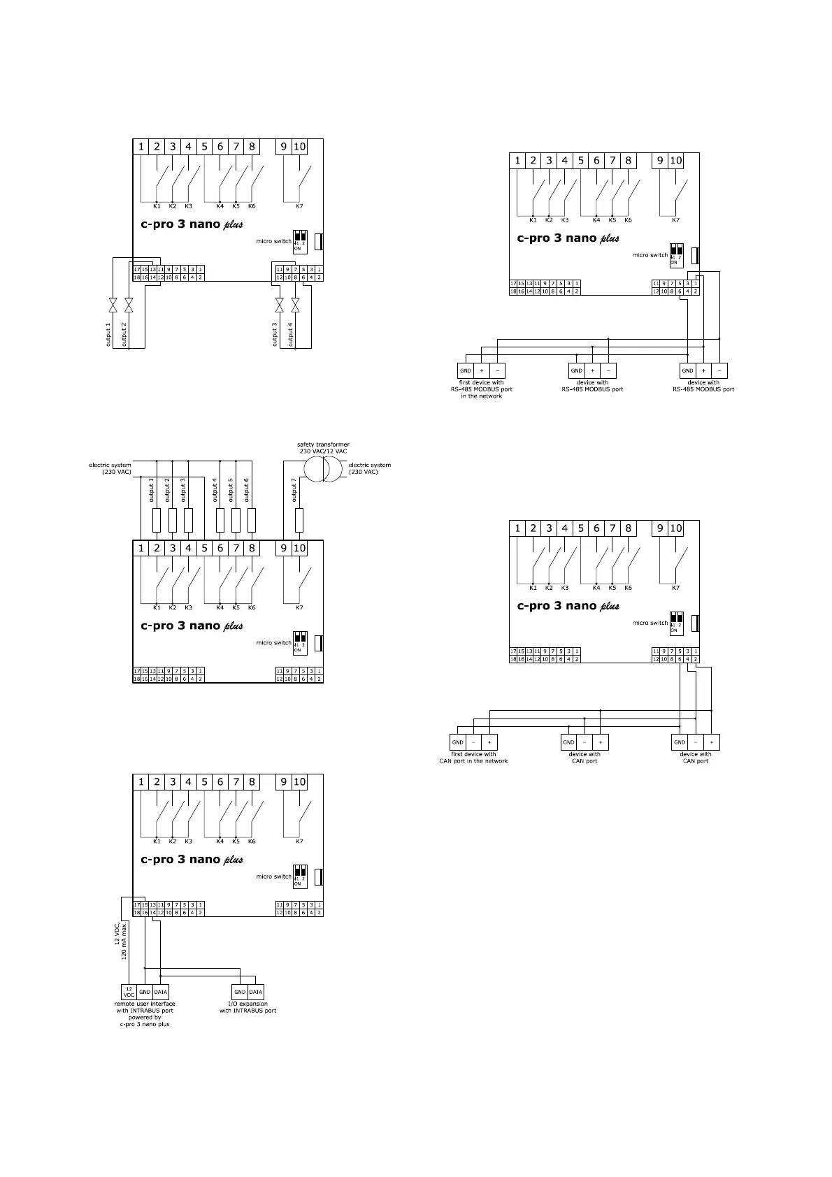
4.5 Analogue output wiring diagram
The picture below shows the c-pro 3 nano plus analogue output connection.
4.6 Digital output wiring diagram
The picture below shows an example of c-pro 3 nano plus digital output
connection.
4.7 INTRABUS port wiring diagram
The picture below shows an example of c-pro 3 nano plus INTRABUS port
connection.
The maximum configuration of the INTRABUS network permits 1
programmable controller, 1 I/O expansion and 1 remote user interface.
4.8 RS-485 MODBUS port wiring diagram
The picture below shows an example of c-pro 3 nano plus RS-485 MODBUS
port connection.
In the example, the c-pro 3 nano plus is the last device on the network with an
RS-485 MODBUS port.
4.9 CAN port wiring diagram
The picture below shows an example of c-pro 3 nano plus CAN port connection.
The maximum CAN network configuration permits 32 devices and it depends
on the BUS load. The BUS load depends on the baud rate and type of device
connected.
The list below gives an example of the CAN network configuration.
- 1 programmable controller
- 4 I/O expansions
- 4 remote user interfaces
- baud rate 500,000 baud.

 Loading...


