www.evco.it
2/2
EV3 200 Web | Controller - Gateway for a network of up to 10 devices
EVCO S.p.A. | EV3 200 Web | 1043W24A3.00
EVCO S.p.A.
Via Feltre 81, 32036, Sedico (BL) ITALIA
Telephone: 0437 8422 | Fax: 0437 83648
Email: info@evco.it | Web: www.evco.it
Disclaimer
This document is the exclusive property of EVCO. It contains a general description and/or a description of
the technical specifications for the services offered by the products listed herein. This document should not
be used to determine the suitability or reliability of these products in relation to specific user applications.
Each user or integration specialist should conduct their own complete and appropriate risk analysis, in
addition to carrying out a product evaluation and test in relation to its specific application or use. Users
can send us comments and suggestions on how to improve or correct this publication.
Neither EVCO nor any of its associates or subsidiaries shall be held responsible or liable for improper use
of the information contained herein.
EVCO has a policy of continuous development. Therefore, EVCO reserves the right to make changes and
improvements to any product described in this document without prior notice.
The technical data in this manual is subject to change without prior notice.
Consider the environment
Please consider the environment before printing this document.
Disposal
The device must be disposed of in accordance with local regulations regarding the
collection of electrical and electronic appliances.
For further information, consult the user manual p/n 114J500E4
downloadable from the website
www.evco.it or scan the QR CODE.
SCAN THE QR CODE AND
READ THE USER MANUAL!
ELECTRICAL CONNECTIONS
DANGER
RISK OF ELECTRIC SHOCK, EXPLOSION OR ELECTRIC ARC
• Various product components, including the printed circuits, run at hazardous voltage levels.
• Only use electrically insulated and suitably calibrated measuring devices and equipment.
• Do not open, disassemble, repair or modify the product.
• Before handling the product, make sure you are wearing all the necessary personal protective
equipment (PPE).
• Do not expose the equipment to liquids or chemicals.
• Use this device and all parts connected to it at the specified voltage only.
• Do not use this equipment for critical safety functions.
FAILURE TO FOLLOW THESE INSTRUCTIONS WILL RESULT IN DEATH OR
SERIOUS INJURY.
DANGER
RISK OF ELECTRIC SHOCK AND FIRE
• Do not use the device with loads greater than those indicated in the technical specifications.
• Do not exceed the temperature and humidity ranges indicated in the technical specifications.
FAILURE TO FOLLOW THESE INSTRUCTIONS WILL RESULT IN DEATH OR
SERIOUS INJURY.
WARNING
MALFUNCTIONING OF THE EQUIPMENT
• Perform the wiring carefully, in compliance with electromagnetic compatibility and safety
requirements.
• Do not operate the product with unknown or incorrect settings or data.
• Make sure the wiring is correct for the final application.
• Use shielded cables for all I/O signal and communication cables.
• Minimise the length of the connections as much as possible and avoid winding the cables
around electrically connected parts.
• The signal cables (analogue and digital inputs, communication and corresponding power
supplies), power cables and power supply cables for the device must be routed separately.
• Before applying the power supply, check all the wiring connections.
• Do not connect wires to unused terminals and/or to terminals labelled “No connection “(N.C.)”.
FAILURE TO FOLLOW THESE INSTRUCTIONS CAN RESULT IN DEATH, SERIOUS
INJURY, OR EQUIPMENT DAMAGE.
Suitable wiring for power supply and I/O SELV
Passo 5,08 mm (0.199 in.)
Ø 3.5 mm (0.14 in.)
mm
2
AWG
0.2…2.5
24…14
0.2…2.5
24…14
0.25…2.5
22...14
2 x 0.25…1
2 x 22…18
2 x 0.2…1.5
2 x 24…16
2 x 0.2…1
2 x 24…18
2 x 0.5...1.5
2 x 20...16
mm
in.
7
0.28
C
0.5...0.6
4.42...5.31
N•m
lb-in
0.25…2.5
22...14
NOTICE
INOPERABLE DEVICE
• When connecting the probes, the digital inputs and the power supply, use cables with a
maximum length of 10 m (32.80 ft).
• When connecting the power supply of the controller and the relay outputs, use cables with
a maximum length of 10 m (32.80 ft.).
FAILURE TO FOLLOW THESE INSTRUCTIONS CAN RESULT EQUIPMENT DAMAGE
.
DIMENSIONS
33 (1.30)
75 (2.95)
69 (2.71)
59 (2.32)
)
INSTALLATION
71
(
2.7
9)
29 (1.14)
mm (in.)
40 (1.57) 40 (1.57)
40 (1.57) 40 (1.57)
WIRING DIAGRAM
1 2 3 4 5 6
1
2
13 14 15
Out2
A+
Out4
Out3
Out1
Power Supply
Maximum 12 A
USB
LT
Pb1
Pb2
ID1
ID3
RS-485
EV3 200 Web
ON
1
2
1
2
13 14 15
RS-485
ETHERNET
ETHERNET
8 9 10 11 12
8 9 10 11 12
1 2 3 4 5 6
B- GND
LD3
LD1
LD2
LD4
ON
1
2
ON
1
2
LT
LT
TERMINALS
1-6 Relay output Out1 (Compressor) 13-14-15 RS-485 serial input
2-6 Relay output Out3 (Fans)
LT
1 ON = Termination resistor inserted
3-6 Relay output Out4 (Defrost) 2 Reserved
4-6 Power supply input USB USB 2.0 input for communication
5-6 Relay output Out2 (AUX)
ETHERNET
RJ45 connector to connect to Ethernet
serial port
8-10 Digital input ID1
LED
LD1 Red
Flashes with messages from
subnetwork
9-10
Digital input ID3 (if P4=0)
Probe input Pb3 (if P4 ≠ 0)
LD2 Green Stays on if connected to EPoCA
LD3 Red Stays on with Ethernet link-up
11-10 Analogue input Pb1 (Temperature) LD4 Green Stays on with Ethernet activity
12-10 Analogue input Pb2 (Evaporator) LED Spenti: No communication
TECHNICAL SPECIFICATIONS
The product complies with the following
harmonised standards:
EN60730-1 and EN60730-2-9
Device construction: Built-in electronic device
Device purpose: Operating control device
Type of action: 1
Pollution category: 2
Overvoltage category: III
Rated impulse withstand voltage: 4000 V
Power supply: 115...230 Vac, ±10%, 50/60 Hz
Consumption: 10 VA maximum
Ambient operating conditions: -10 ... 50 °C (14 ... 122 °F) 10 … 90 % RH non-condensing
Transportation and storage conditions: -20 ... 70 °C (-4 ... 158 °F) 10 … 90 % RH non-condensing
Software class: A
Environmental front protection: IP65
Clock (RTC): Built-in lithium battery
Clock drift: ≤ 60 s/month at 25 °C (77 °F)
Battery life: 30 days
Battery charging time: 24 h through device’s power supply
Data memory: 32 MB
Data memory per device: ~2.7 MB
OTHER TECHNICAL INFORMATION
Digital inputs: 2 voltage-free digital inputs
Analogue inputs for temperature: 2 analogue inputs for NTC probes
Digital output with non-hazardous voltage (SELV): 4 relay outputs
Serial: 1 Ethernet RJ45 10/100 MAC serial port
1 USB serial port
ANALOGUE INPUT FEATURES
Default
NTC 10 kΩ at 25
°C BETA 3435
PTC KTY 81-121
990 Ω at 25 °C
RH
Digital
input
Pb1
Probe Temperature
• --- --- ---
Pb2
Probe Evaporator
• --- --- ---
Range ---
-40...105 °C
(-40...220 °F)
--- --- ---
Resolution --- 0.1 °C (1 °F) --- --- ---
Input impedance --- 10 kΩ --- --- ---
DIGITAL OUTPUT FEATURES
Default Description Load (at 250 Vac) Type of load
Out1 Compressor SPDT 16 A Resistive
Out2 AUX SPDT 5 A Resistive
Out3 Fans SPDT 5 A Resistive
Out4 Not configured SPDT 8 A Resistive
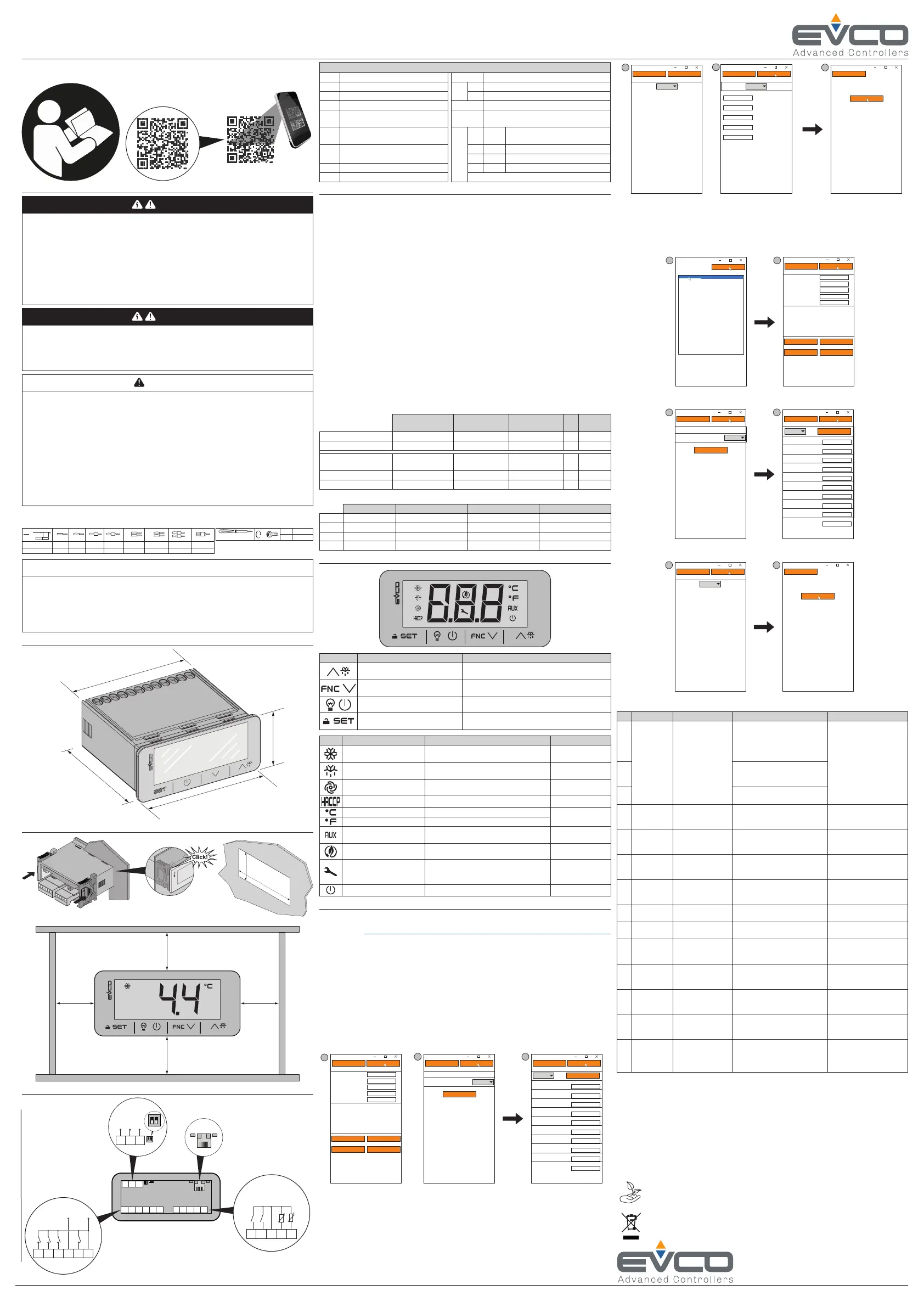
USER INTERFACE
Key... Press once... Hold down...
• Scroll up through values
• Move within a menu
Activate manual defrost
• Scroll down through values
• Move within a menu
Access the FNC functions menu (functions activated
by key)
Manually activate the light relay Switch the device on/off (stand-by)
• Conrm values on the display
• Set the setpoint
Enter the parameter menu
Icon ON... Flashing... OFF...
Compressor ON
• Protection delay compressor ON
• Setpoint being changed
Compressor OFF
• Defrost ON
• Pre-dripping ON
• Defrost delay ON
• Dripping ON
---
Evaporator fans ON
Evaporator fan activation delay ON
Evaporator fans OFF
HACCP alarm saved New HACCP alarm recorded ---
Temperature displayed in °C ---
• Over-heating ON
• Over-cooling ON
Temperature displayed in °F ---
• AUX function ON
• AUX digital output ON
--- AUX function OFF
Energy saving ON --- Energy saving OFF
Compressor maintenance
request
• Parameters being changed
• Access to FNC menu (functions activated by key)
• Active connection with EVconnect
---
Device off --- Device on
REMOTE COMMUNICATION CONFIGURATION
EV3 200 Web can be configured to connect with EPoCA in two different ways:
•
From a PC (Windows only) through EPoCA.exe (online/ofine) which can be downloaded from
the website: https://www.evco.it/assets/doc/EVCO-EV3200Web_congurator_for_EPoCA.zip
• From a smartphone/tablet using the EVLink Wi-Fi app.
In both cases, the devices must be visible on the local network. If the local network requires a
static IP address, configure using the micro-B USB cable.
If used in a subnetwork, configure the BLE parameter for every device from 1 to 10 before
searching on the network.
NOTE: For more information regarding the possible congurations of remote communication,
scan the QR code in this instruction sheet and read the user manual.
Conguration using PC (
Connecting using a micro-B USB cable)
1. Connect the micro-B USB cable from the PC to the device;
2. Make sure EPoCA.exe has been installed in the PC;
3. Boot up EPoCA.exe;
4. Set the Plant and Device data, save the conguration by pressing Save Cong. and continue
by pressing Next;
3
Next
Prev
1. Plant Configuration
EPOCA
Plant Name:
Plant Password:
Plant Category:
Device Name:
Serial Code:
Plant ID:
Build:
Last Reset:
Mac address:
Internet Status:
Save Config.
Export plant fileUpload plant file
Erase Config.
4 5
Next
Prev
2. Date and Time
EPOCA
Day, NN MM YYYY hh:mm:ss
Daylight saving time
Addr. 1
Off
Set local time
Next
Prev
3. Controllers
EPOCA
Autoaddress
Com1
On Line
On Line
Off Line
Off Line
Off Line
Off Line
Off Line
Off Line
Off Line
Off Line
Name Name
Name
Addr. 2
Addr. 3
Addr. 4
Addr. 5
Addr. 6
Addr.7
Addr. 8
Addr. 9
Addr. 10
Name
Name
Name
Name
Name
Name
Name
Name
Name
5. Set the date, time and local time used and press Next;
6. Set the name of the controllers connected via RS-485 to EV3 200 Web and press Next;
7. Set the type of IP address and press Next;
8. Press Congure to complete conguration of the device.
6 7
Next
Prev
4. IP Address
EPOCA
IP address:
Dynamic
Next
Prev
EPOCA
Configure
Next
Prev
4. IP Address
EPOCA
Static
IP address
Netmask
Gateway
Dns 1
Dns 2
0.0.0.0
0.0.0.0
0.0.0.0
0.0.0.0
0.0.0.0
6
Conguration using PC (Connecting using an Ethernet cable with connection to modem)
1. Make sure EPoCA.exe has been installed in the PC;
2. Boot up EPoCA.exe, the programme scans the local network (LAN) which the PC is
connected to to detect the devices;
3. Select the device to congure and press Next;
4. Set the Plant and Device data, save the conguration by pressing Save Cong. and continue
by pressing Next;
3 4
Next
Device selection
Device web page
EPOCA
EPOCAAXXXXX
Next
Prev
1. Plant Configuration
EPOCA
Plant Name:
Password:
Plant Category:
Device Name:
Serial Code:
Plant ID:
Build:
Last Reset:
Mac address:
Internet Status:
Save Config.
Export plant fileUpload plant file
Erase Config.
5. Set the date, time and local time used and press Next;
6. Set the name of the controllers connected via RS-485 to EV3 200 Web and press Next;
5 6
Next
Prev
2. Date and Time
EPOCA
Day, NN MM YYYY hh:mm:ss
Daylight saving time
Addr. 1
Off
Set local time
Next
Prev
3. Controllers
EPOCA
Autoaddress
Com1
On Line
On Line
Off Line
Off Line
Off Line
Off Line
Off Line
Off Line
Off Line
Off Line
Name Name
Name
Addr. 2
Addr. 3
Addr. 4
Addr. 5
Addr. 6
Addr.7
Addr. 8
Addr. 9
Addr. 10
Name
Name
Name
Name
Name
Name
Name
Name
Name
Set the type of IP address and press Next;
7. Press Congure to complete conguration of the device.
7 8
Next
Prev
4. IP Address
EPOCA
IP address:
Dynamic
Next
Prev
EPOCA
Configure
Cod.
Description Cause Effects Resolution
Pr1
Probe error
• Probe not working
• Probe incorrectly
connected
• Incorrect type of
probe
• Code Pr1 displayed
• Alarm output ON
• Compressor regulated
according to C4 and C5
• Defrost suspended
• Check the type of probe
(PO)
• Check probe wiring
• Change type of probe
Pr2
• Code Pr2 displayed
• Alarm output ON
• If P4 = 1, defrost active for time d3
Pr3
• Code Pr3 displayed
• No effect on regulation
rtc
Clock alarm
Clock (RTC) alarm
not working
Clock-connected functions not
present or not synchronised with
the actual time
Set the right time.
If the error persists, replace
the device (RTC battery dead)
AL
Low
temperature
alarm Pb1
Temperature Pb1 >
A1 for a time = A7
• Code AL displayed
• No effect on regulation
Wait until the temperature
read by Pb1 goes below the
alarm threshold (A1-A11)
AH
High
temperature
alarm Pb1
Temperature Pb1 >
A4 for a time = A7
• Code AH displayed
• No effect on regulation
Wait until the temperature
read by Pb1 goes above the
alarm threshold (A4+A11)
id
Door open
alarm
Digital input
activated for a
time > i2
• Code id displayed
• Regulators blocked depending on
the current function in iC1 = 7, 8 or 9
• If i2 = -1 the alarm is
disabled;
• Check i2 and iP1
PF
Power outage
alarm
Power outage for
longer than A10
Code PF is recorded
Check the power supply
wiring
COH
Cond. overheat
signal
Condenser
temperature > C6
• Code COH displayed
• No effect on regulation
Check C6
CSd
High
condensation
alarm
Condenser
temperature > C7
for a time = C8
• Code CSd displayed
• Compressor locked
• Switch the device off then
on again;
• Check C7 and C8
iA
Multi-
purpose
input alarm
Digital input
activated (iC1 = 2)
for a time = i5
• Code iA displayed
• No effect on regulation
Check i5 and i6
CtH
Compressor
thermal
switch alarm
Digital input
activated (iC1 = 5)
The regulator counts the number
of events i8 in the time i7 from
the rst one
• If i7 = 0 alarm is always
automatically reset
• Check i5 and i6
th
Thermal
switch global
alarm
Digital input
activated (iC1 = 5)
The regulator counts the number
of events i8 in the time i7 from
the rst one
• Switch the device off then
on again;
• Check i5 and i6
dFd
Defrost
timeout
alarm
Defrost terminated
due to timeout and
not to reaching
temperature d2
• Code dFd displayed
• No effect on regulation
• Touch any key
• Check d2, d3 and d11
 Loading...