EVCO S.p.A. | EVJ254 | Instruction sheet ver. 1.0 | Code 104J254I103 | Page 3 of 4 | PT 13/18
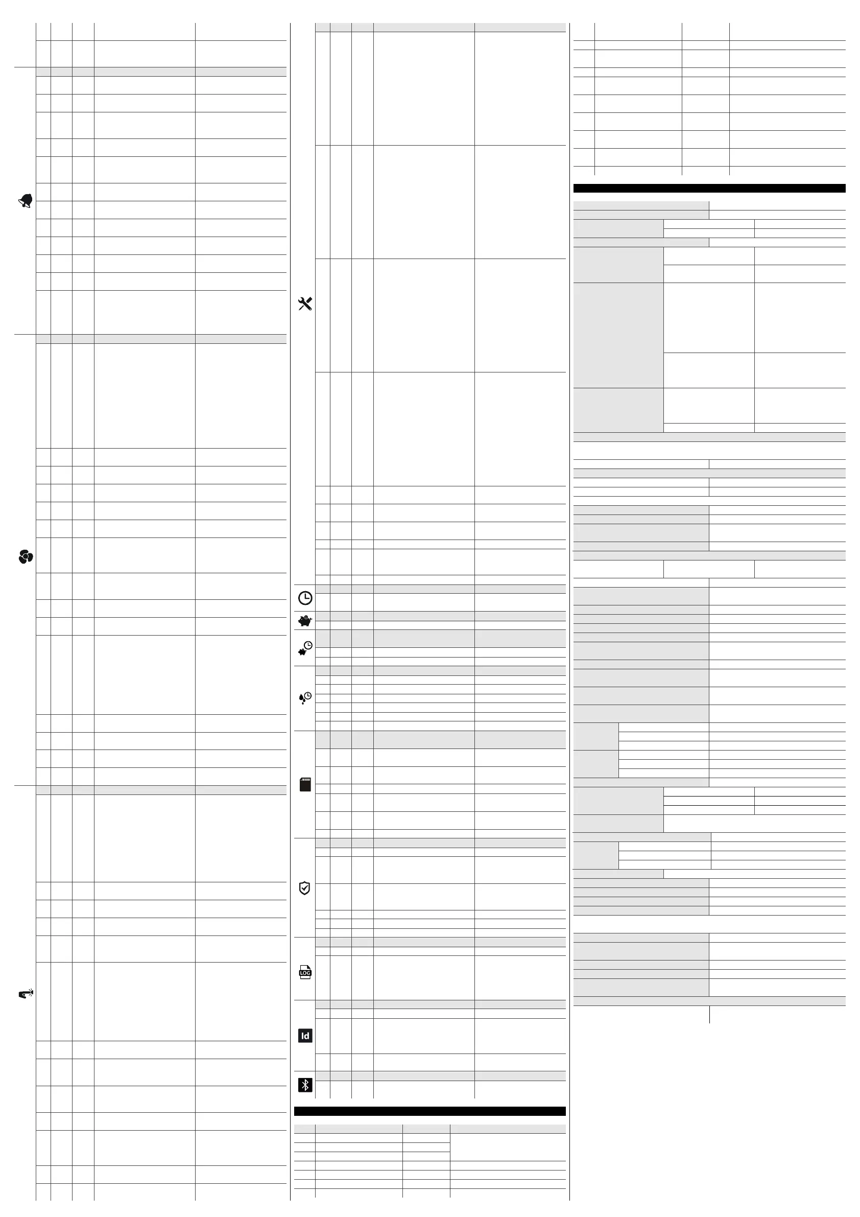
55
d25
0
enable air out probe for defrost
during evaporator probe alarm
0 = no 1 = yes
56
d26
6
defrost interval during
evaporator probe alarm
0... 99 h
0 = only manual
if d25 = 1
N.
PAR.
DEF.
ALARMS
MIN... MAX.
57
A0
0
select value for high/low
temperature alarms
0 = regulation temperature
1 = evaporator temperature
58
A1
0.0
threshold for low temperature
alarm
-99... 99 °C/°F
59
A2
0
low temperature alarm type
0 = disabled
1 = relative to setpoint
2 = absolute
60
A4
0.0
threshold for high temperature
alarm
-99... 99 °C/°F
61
A5
0
high temperature alarm type
0 = regulation temperature
1 = evaporator temperature
2 = auxiliary temperature
62
A6
120
high temperature alarm delay
after power-on
0... 240 min
63
A7
15
high/low temperature alarms
delay
0... 240 min
64
A8
15
high temperature alarm delay
after defrost
0... 240 min
65
A9
15
high temperature alarm delay
after door closing
0... 240 min
66
A10
10
power failure duration for alarm
recording
0... 240 min
67
A11
2.0
high/low temperature alarms
reset differential
1... 15 °C/°F
68
A12
1
power failure alarm notification
type (not available in EVJ254N7)
0 = HACCP LED
1 = HACCP LED + PF label +
buzzer
2 =
HACCP LED + PF label +
buzzer (if duration > A10)
N. PAR. DEF. FANS MIN... MAX.
69
F0
1
evaporator fan mode during
normal operation
0 = off 1 = on
2 = on if compressor on
3 = thermoregulated (with
regulation temperature
+ F1)
4 = thermoregulated (with
regulation temperature
+ F1) if compressor on
5 = according to F6
6 =
thermoregulated (with F1)
7 = thermoregulated (with
F1) if compressor on
70
F1
-4.0
threshold for evaporator fan
operation
-99... 99 °C/°F
71
F2
0
evaporator fan mode during
defrost and dripping
0 = off 1 = on
2 = according to F0
72
F3
2
evaporator fan off maximum
time
0... 15 min
73
F4
30
evaporator fan off time during
energy saving
0... 240 s x 10
if F0 ≠ 5
74
F5
30
evaporator fan on time during
energy saving
0... 240 s x 10
if F0 ≠ 5
75
F6
0
high/low humidity operation
0 = low humidity (with F17
and F18 if compressor
off, on if compressor on)
1 = high humifity (on)
76
F7
5.0
threshold for evaporator fan on
after dripping (relative to
setpoint)
-99... 99 °C/°F
setpoint + F7
77
F8
2.0
threshold for evaporator fan
operation differential
1... 15 °C/°F
78
F9
10
evaporator fan off delay after
compressor off
0... 240 s
if F0 = 2 or 5
79
F10
1
condenser fan mode
0 =
thermoregulated (with F11)
1 = thermoregulated (with
F11) if compressor off,
on if compressor on
2 = thermoregulated (with
F11) if compressor off,
on if compressor on, off
during defrost, pre-
dripping and dripping
80
F11
15.0
threshold for condenser fan on
0... 99 °C/°F
differential = 2 °C/4 °F
81
F12
30
condenser fan off delay after
compressor off
0... 240 s
if P4 ≠ 1
82
F17
60
evaporator fan off time with low
humidity
0... 240 s
83
F18
10
evaporator fan on time with low
humidity
0... 240 s
N. PAR. DEF. DIGITAL INPUTS MIN... MAX.
84
i0
5
door switch input function
0 = disabled
1 = compressor +
evaporator fan off
2 = evaporator fan off
3 = cabinet light on
4 = compressor +
evaporator fan off,
cabinet light on
5 = evaporator fan off +
cabinet light on
85
i1
0
door switch input activation
0 = with contact closed
1 = with contact open
86
i2
30
open door alarm delay
-1... 120 min
-1 = disabled
87
i3
15
regulation inhibition maximum
time with door open
-1... 120 min
-1 = until the closing
88
i4
0
enable open door alarm
recording (not available in
EVJ254N7)
0 = no 1 = yes
if i2 ≠ -1 and after i2
89
i5
8
multi-purpose input function
0 = disabled
1 = energy saving
2 = iA alarm
3 = iSd alarm
4 =
button-operated load 1 on
5 =
button-operated load 2 on
6 = device on/off
7 = LP alarm
8 = C1t alarm
90
i6
0
multi-purpose input activation
0 = with contact closed
1 = with contact open
91
i7
0
multi-purpose input alarm delay
0... 120 min
if i5 = 3 or 7, compressor on
delay after alarm reset
92
i8
0
number of multi-purpose input
activations for high pressure
alarm
0... 15
0 = disabled
if i5 = 3
93
i9
240
reset counter time for high
pressure alarm
1... 999 min
94
i10
0
door closed consecutive time for
energy saving
0... 999 min
after regulation temperature
< SP
0 = disabled
95
i13
180
number of door openings for
defrost
0... 240
0 = disabled
96
i14
32
door open consecutive time for
defrost
0... 240 min
0 = disabled
N. PAR. DEF. DIGITAL OUTPUTS MIN... MAX.
97
u1c
2
relay K1 configuration
0 = compressor
1 = evaporator fan
2 = condenser fan
3 = defrost
4 = cabinet light
5 = demisting
6 = door heaters
7 = heater for neutral zone
8 = dripping heater
9 = button-operated load 1
10 = button-operated load 2
11 = alarm
12 = on/stand-by
98
u2c
3
relay K2 configuration
0 = compressor
1 = evaporator fan
2 = condenser fan
3 = defrost
4 = cabinet light
5 = demisting
6 = door heaters
7 = heater for neutral zone
8 = dripping heater
9 = button-operated load 1
10 = button-operated load 2
11 = alarm
12 = on/stand-by
99
u3c
4
relay K3 configuration
0 = compressor
1 = evaporator fan
2 = condenser fan
3 = defrost
4 = cabinet light
5 = demisting
6 = door heaters
7 = heater for neutral zone
8 = dripping heater
9 = button-operated load 1
10 = button-operated load 2
11 = alarm
12 = on/stand-by
100
u4c
1
relay K4 configuration
0 = compressor
1 = evaporator fan
2 = condenser fan
3 = defrost
4 = cabinet light
5 = demisting
6 = door heaters
7 = heater for neutral zone
8 = dripping heater
9 = button-operated load 1
10 = button-operated load 2
11 = alarm
12 = on/stand-by
101
u2
0
enable cabinet light and button-
operated load in stand-by
0 = no 1 = yes
manual
102
u4
1
enable alarm output off silencing
the buzzer
0 = no 1 = yes
103
u5
-1.0
threshold for door heaters on
-99... 99 °C/°F
differential = 2 °C/4 °F
104
u6 5 demisting on duration 1... 120 min
105
u7
-5.0
neutral zone threshold for
heating (relative to setpoint)
-99... 99 °C/°F
differential = 2 °C/4 °F
setpoint + u7
106
u9 1 enable alarm buzzer 0 = no 1 = yes
N. PAR. DEF. REAL TIME CLOCK MIN... MAX.
107
Hr0
1
enable clock (default 0 in
EVJ254N7)
0 = no 1 = yes
N. PAR. DEF. ENERGY SAVING (if r5 = 0) MIN... MAX.
108
HE2 0 energy saving maximum duration
0... 999 min
N.
PAR.
DEF.
REAL TIME ENERGY SAVING (if
r5 = 0)
MIN... MAX.
109
H01 0 energy saving time 0... 23 h
110
H02 0 energy saving maximum duration
0... 24 h
N. PAR. DEF. REAL TIME DEFROST (if d8 = 4) MIN... MAX.
111
Hd1 h- 1st daily defrost time h- = disabled
112
Hd2 h- 2nd daily defrost time h- = disabled
113
Hd3 h- 3rd daily defrost time h- = disabled
114
Hd4 h- 4th daily defrost time h- = disabled
115
Hd5 h- 5th daily defrost time h- = disabled
116
Hd6 h- 6th daily defrost time h- = disabled
N.
PAR.
DEF.
DATA-LOGGING (not available in
EVJ254N7)
MIN... MAX.
117
Sd0
30
SD card writing interval in HACCP
mode
1... 30 min
118
Sd1
1
SD card writing interval in
service mode
1... 30 min
119
Sd2 60 service mode duration 1... 240 min
120
Sd3
0
enable critical temperature
recording
0 = no 1 = yes
121
Sd4
0
enable cabinet temperature
recording
0 = no 1 = yes
122
Sd5 1 decimal separator type 0 = comma 1 = point
N. PAR. DEF. SAFETIES MIN... MAX.
123
POF 1 enable ON/STAND-BY key 0 = no 1 = yes
124
Loc
1
enable keypad lock (default 0 in
the models with open-frame user
interface)
0 = no 1 = yes
125
Sen
90
sensitivity capacitive keyboard
(available in the models installed
from behind)
60... 120
60 = very sensitive
126
PAS -19 password -99... 999
127
PA1 426 level 1 password -99... 999
128
PA2 824 level 2 password -99... 999
N. PAR. DEF. DATA-LOGGING EVLINK MIN... MAX.
129
rE0 60 data-logger sampling interval 0... 240 min
130
rE1
4
recorded temperature
0 = none 1 = cabinet
2 = evaporator
3 = auxiliary
4 = cabinet and evaporator
5 = all
N. PAR. DEF. MODBUS MIN... MAX.
131
LA 247 MODBUS address 1... 247
132
Lb
2
MODBUS baud rate
0 = 2,400 baud
1 = 4,800 baud
2 = 9,600 baud
3 = 19,200 baud
133
LP
2
parity
0 = none 1 = odd
2 = even
N. PAR. DEF. BLUETOOTH MIN... MAX.
131
4
bLE 1 enable Bluetooth 0 = no 1 = yes
9 ALARMS
COD.
DESCRIPTION
RESET
TO CORRECT
Pr1 cabinet probe alarm automatic
- check P0
Pr2
evaporator probe alarm automatic
- check probe integrity
Pr3 auxiliary probe alarm automatic
- check electrical connection
rtc clock alarm manual set date, time and day of the week
AL low temperature alarm automatic
check A0, A1 and A2
AH high temperature alarm automatic
check A4 and A5
id open door alarm automatic
check i0 and i1
PF
power failure alarm
manual
- touch a key
- check electrical connection
COH high condensation warning automatic check C6
CSd
high condensation alarm
manual
- switch the device off and on
- check C7
iA multi-purpose input alarm automatic check i5 and i6
iSd
high pressure alarm
manual
- switch the device off and on
- check i5, i6, i8, i9
LP
low pressure alarm
automatic
check i5 and i6
C1t
compressor thermal switch
alarm
automatic
check i5 and i6
dFd
defrost timeout alarm
manual
- touch a key
- check d2, d3 and d11
FUL
SD card full alarm
manual
free up space on the SD card or
replace it
Sd No SD card inserted alarm
manual insert the SD card or replace it
10 TECHNICAL SPECIFICATIONS
Purpose of the control device
Function controller
Construction of the control device
Built-in electronic device
Container Models in plastic container
Black, self-extinguishing
Open-frame models
Open-frame board
Category of heat and fire resistance
D
Measurements
Models in plastic container
111.4 x 76.4 x 48.0 mm
(4 3/8 x 3 x 1 15/16 in)
Open-frame models
101.0 x 67.0 x 47.0 mm
(4 x 2 5/8 x 1 7/8 in)
Mounting methods for the
control device
Models in plastic container
according to the model, front
installation on a plastic or
metal panel (with elastic
holding flaps) or installed
from behind a glass or
methacrylate panel (with
biadhesive) customizing the
keys on the front of the unit
Open-frame models
To be installed from behind,
with threaded studs and
membrane keypad (not
provided)
Degree of protection
provided by the covering
Models in plastic container
IP65 (front), on condition the
device is fitted to a metal
panel with thickness 0.8 mm
(1/32 in)
Open-frame models
IP00
Connection method
Fixed screw terminal blocks for wires up to 2.5 mm² (removable screw terminal blocks for
wires up to 2,5 mm² by request)
Pico-Blade connector
Micro-MaTch connector
Maximum permitted length for connection cables
Power supply: 10 m (32.8 ft)
Analogue inputs: 10 m (32.8 ft)
Digital inputs: 10 m (32.8 ft) Analogue outputs: 3 m (9.84 ft)
Digital outputs: 10 m (32.8 ft)
Operating temperature
From -5 to 55 °C (from 23 to 131 °F)
Storage temperature
From -25 to 70 °C (from -13 to 158 °F)
Operating humidity
Relative humidity without condensate from
10 to 90%
Pollution status of the control device
2
Conformity
RoHS 2011/65/CE
WEEE 2012/19/EU
REACH (EC) Regulation
1907/2006
EMC 2014/30/UE LVD 2014/35/UE
Power supply
230 VAC (+10% -15%), 50/60 Hz (±3 Hz),
max. 6 VA insulated
Earthing methods for the control device
None
Rated impulse-withstand voltage
2.5 KV
Over-voltage category
II
Software class and structure
A
Clock
Incorporated secondary lithium battery
(clock
not available in EVJ254N7)
Clock drift
≤ 60 s/month at 25 °C (77 °F)
Clock battery autonomy in the absence of a
power supply
> 24 h at 25 °C (77 °F)
Clock battery charging time
24 h (the battery is charged by the power
supply of the device)
Analogue inputs
2 for PTC or NTC probes (cabinet probe and
evaporator probe)
PTC probes
Sensor type
KTY 81-121 (990 @ 25 °C, 77 °F)
Measurement field
From -50 to 150 °C (from -58 to 302 °F)
Resolution
0.1 °C (1 °F)
NTC probes
Sensor type
ß3435 (10 K @ 25 °C, 77 °F)
Measurement field
From -40 to 105 °C (from -40 to 221 °F)
Resolution
0.1 °C (1 °F)
Digital inputs
1 dry contact (door switch)
Dry contact
Contact type
5 VDC, 1.5 mA
Power supply
None
Protection
None
Other inputs
Input configurable for analogue input (auxiliary probe) or
digital input (multi-purpose input)
Analog outputs 1 for PWM signal (compressor inverter)
PWM signal Output 9.5... 19 VDC, 10 mA
Frequency 0... 150 Hz
Protection None
Digital outputs 4 with electro-mechanical relay
Relay K1
SPST, 16 A res. @ 250 VAC
Relay K2
SPDT, 8 A res. @ 250 VAC
Relay K3
SPST, 8 A res. @ 250 VAC
Relay K4
SPST, 5 A res. @ 250 VAC
The device guarantees double insulation between each digital output connector and the rest
of the components of the device
Type 1 or Type 2 Actions
Type 1
Additional features of Type 1 or Type 2
actions
C
Displays
Custom display, 3 digit, with function icons
Alarm buzzer
Incorporated
Incorporated sensors:
Bluetooth Low Energy (available in
EVJ254N7VXXRXV).
Communications ports
1 TTL MODBUS slave port for EVconnect APP
or BMS
1 port for SD card data-logger module
EVBD05 (not available in EVJ254N7)

 Loading...