12
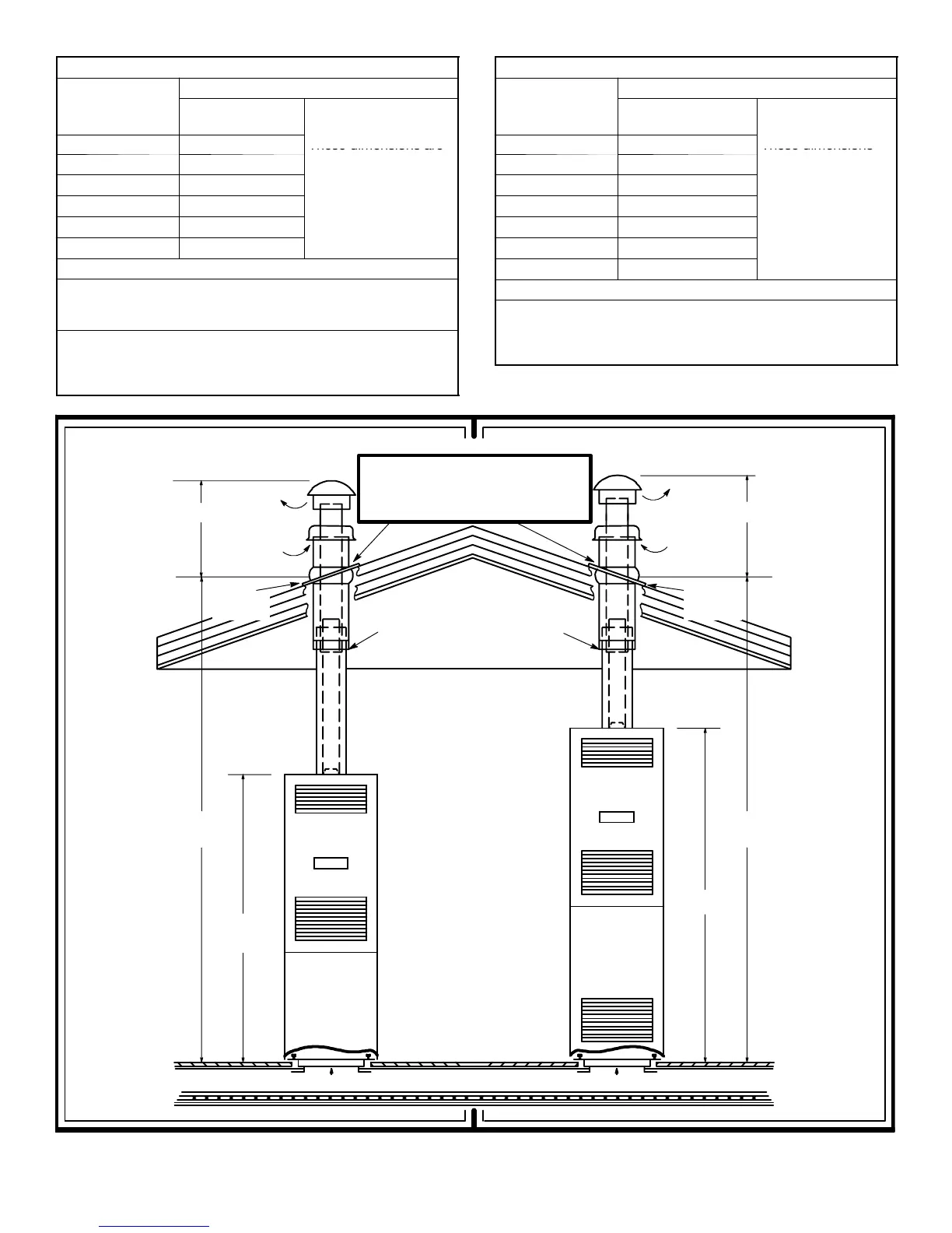
TABLE 4 — DLAS Roof Jacks
Roof Jack
Installation Dimensions
Model
Number
¡
Adjustable Height
4000---7121/C 75” to 86”
These dimensions are
4000---7141/C ** 83” to 104”
from the floor to the
4000---7151/C ** 90” to 116”
top side of the roo
.
4000---7171/C 127” to 157”
.
4000---8161/C *+ 85” to 101”
4000---8181/C *+ 99” to 129”
* These jacks have removable crowns.
Note: It is recommended that the 7900---6171 (17”) Interior
extension be used with these models. If used refer to TABLE 5
for sizing of roof jack.
** Available with 3 ---1/2, 12 Pitch Fixed Flashing.
Models 4000---6141 and 4000 ---6151
+ Available with 3--- 1/2, 12 Pitch Fixed Flashing.
Models 4000---9161 and 4000 ---9181
TABLE 5 — DGAT & DGAM Roof Jacks
Roof Jack
Installation Dimensions
Model
Number
¡
Adjustable Height
4000---7101/C 86” to 95”
These dimensions
4000---7121/C 91” to 102”
are from the floor to
4000---7141/C ** 99” to 120”
the top side o
the
4000---7151/C ** 106” to 132”
.
.
4000---7171/C 143” to 173”
4000---8161/C *+ 101” to 117”
4000---8181/C *+ 115” to 145”
* These jacks have removable crowns.
** Available with 3 ---1/2, 12 Pitch Fixed Flashing.
Models 4000---6141 and 4000 ---6151
+ Available with 3--- 1/2, 12 Pitch Fixed Flashing.
Models 4000---9161 and 4000 ---9181
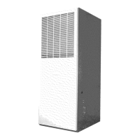
ROOF FLANGE IS ADJUSTABLE UP TO 23˚ ( 5 --- 1 2 P I T C H )
WARM AIR DUCTDUCT CONNECTOR
ROOF
76”
CAUL K CAREFULLY ALL AROUND
SWIVEL JOINT WITH SEALANT
SUPPLIED BY FURNACE
MANUFACTURER.
IMPORTANT
SEAL ROOF JACK FLASHING TO THE
ROOF JACK AND ROOF.
THIS IS THE INSTALLER’S RESPONSIBIL-
ITY.
60--- 1/2”
WARM AIR DUCT DUCT CONNECTOR
FLOOR
FLUE
GASE
S
COMBUS-
TION
AIR
CAULK
UNDER
FLASHING
The Bead or End of Upper Por-
tion of Roof Jack need Not ex-
tend below the ceiling.
(INCLUDES
SUB ---BASE)
19 1/2”
CAULK
UNDER
FLASHING
¡¡
FLUE
GASE
S
COMBUS-
TION
AIR
19 1/2”
Figure 8 — DLAS Models
Figure 9
DG
T&DG
MModels
NOTE: