035-15266-003Rev.A(0804)
PARALLELDUCTSYSTEM
TheEBDuctConnectorInsert37323716001maybeusedon
EBSeriesElectricManufacturedHousingFurnaceswhere
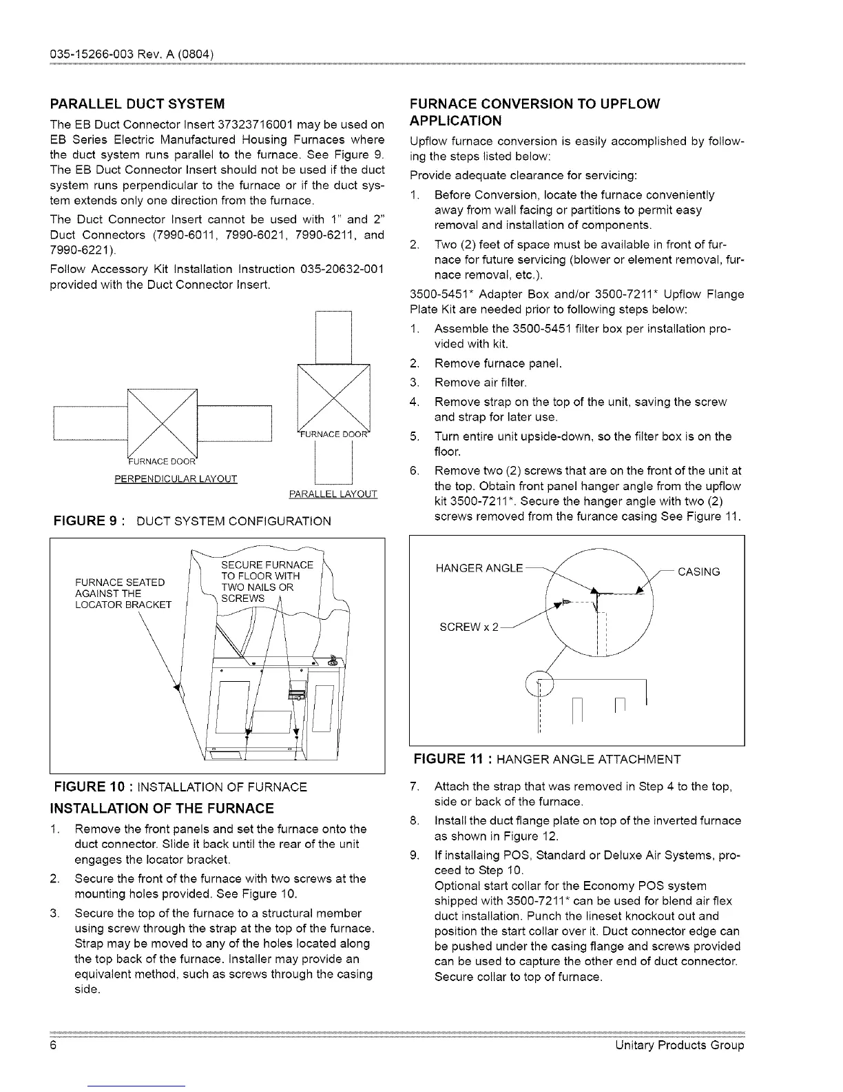
theductsystemrunsparalleltothefurnace.SeeFigure9.
TheEBDuctConnectorInsertshouldnotbeusediftheduct
systemrunsperpendiculartothefurnaceoriftheductsys-
temextendsonlyonedirectionfromthefurnace.
TheDuctConnectorInsertcannotbeusedwith 1" and 2"
Duct Connectors (7990-6011, 7990-6021, 7990-6211, and
7990-6221 ).
Follow Accessory Kit Installation Instruction 035-20632-001
provided with the Duct Connector Insert.
JRNACE DOO
PERPENDICULAR LAYOUT
PARALLEL LAYOUT
FIGURE 9 : DUCT SYSTEM CONFIGURATION
FURNACE CONVERSION TO UPFLOW
APPLICATION
Upfiow furnace conversion is easily accomplished by follow-
ing the steps listed below:
Provide adequate clearance for servicing:
1. Before Conversion, locate the furnace conveniently
away from wall facing or partitions to permit easy
removal and installation of components.
2. Two (2) feet of space must be available in front of fur-
nace for future servicing (blower or element removal, fur-
nace removal, etc.).
3500-5451" Adapter Box and/or 3500-7211" Upflow Flange
Plate Kit are needed prior to following steps below:
1. Assemble the 3500-5451 filter box per installation pro-
vided with kit.
2. Remove furnace panel.
3. Remove air filter.
4. Remove strap on the top of the unit, saving the screw
and strap for later use.
5. Turn entire unit upside-down, so the filter box is on the
floor.
6. Remove two (2) screws that are on the front of the unit at
the top. Obtain front panel hanger angle from the upflow
kit 3500-7211 *. Secure the hanger angle with two (2)
screws removed from the furance casing See Figure 11.
FURNACE SEATED
AGAINST THE
LOCATOR BRACKET
FIGURE 10 : INSTALLATIONOF FURNACE
INSTALLATION OF THE FURNACE
1. Remove the front panels and set the furnace onto the
duct connector. Slide it back until the rear of the unit
engages the Iocator bracket.
2. Secure the front of the furnace with two screws at the
mounting holes provided. See Figure 10.
3. Secure the top of the furnace to a structural member
using screw through the strap at the top of the furnace.
Strap may be moved to any of the holes located along
the top back of the furnace. Installer may provide an
equivalent method, such as screws through the casing
side.
7.
8.
9.
HANGER ANGLE _.
SCREW x 2
FIGURE 11 : HANGER ANGLE ATTACHMENT
Attach the strap that was removed in Step 4 to the top,
side or back of the furnace.
Install the duct flange plate on top of the inverted furnace
as shown in Figure 12.
If installaing POS, Standard or Deluxe Air Systems, pro-
ceed to Step 10.
Optional start collar for the Economy POS system
shipped with 3500-7211" can be used for blend air flex
duct installation. Punch the lineset knockout out and
position the start collar over it. Duct connector edge can
be pushed under the casing flange and screws provided
can be used to capture the other end of duct connector.
Secure collar to top of furnace.
6 Unitary Products Group