035-15266-003Rev.A(0804)
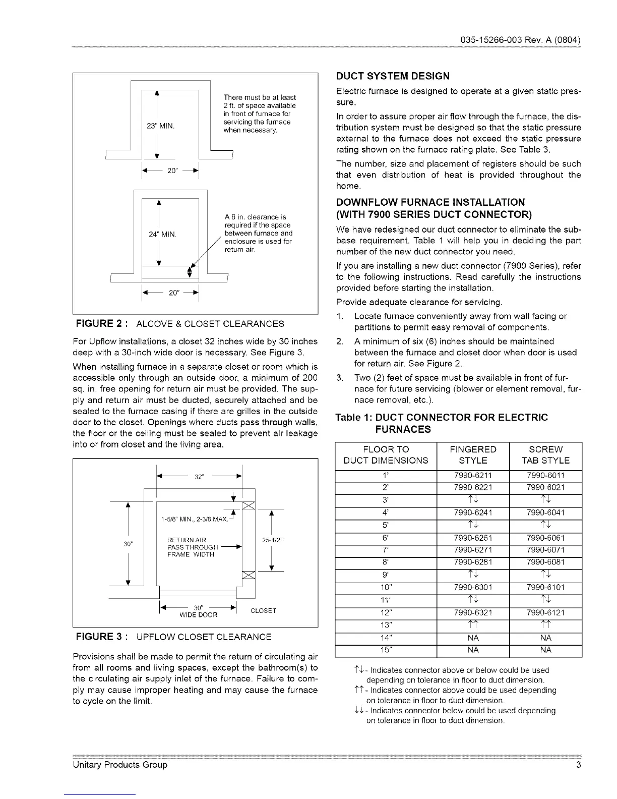
23" MIN.
_ 20" _
There must be at least
2 ft. of space available
in front of furnace for
servicing the furnace
when necessary.
24" MIN.
/
f-
A 6 in. clearance is
required if the space
between furnace and
J enclosure is used for
return air,
FIGURE 2 : ALCOVE & CLOSET CLEARANCES
For Upflow installations, a closet 32 inches wide by 30 inches
deep with a 30-inch wide door is necessary. See Figure 3.
When installing furnace in a separate closet or room which is
accessible only through an outside door, a minimum of 200
sq. in. free opening for return air must be provided. The sup-
ply and return air must be ducted, securely attached and be
sealed to the furnace casing if there are grilles in the outside
door to the closet. Openings where ducts pass through walls,
the floor or the ceiling must be sealed to prevent air leakage
into or from closet and the living area.
30"
32"
1-5/8" MIN., 2-3/8 MAX. _
RETURN AIR
PASS THROUGH
FRAME WIDTH
25-1/2 ....
I
30" _1 CLOSET
WIDE DOOR
FIGURE 3 • UPFLOW CLOSET CLEARANCE
Provisions shall be made to permit the return of circulating air
from all rooms and living spaces, except the bathroom(s) to
the circulating air supply inlet of the furnace. Failure to com-
ply may cause improper heating and may cause the furnace
to cycle on the limit.
DUCT SYSTEM DESIGN
Electric furnace is designed to operate at a given static pres-
sure.
In order to assure proper air flow through the furnace, the dis-
tribution system must be designed so that the static pressure
external to the furnace does not exceed the static pressure
rating shown on the furnace rating plate. See Table 3.
The number, size and placement of registers should be such
that even distribution of heat is provided throughout the
home.
DOWNFLOW FURNACE INSTALLATION
(WITH 7900 SERIES DUCT CONNECTOR)
We have redesigned our duct connector to eliminate the sub-
base requirement. Table 1 will help you in deciding the part
number of the new duct connector you need.
If you are installing a new duct connector (7900 Series), refer
to the following instructions. Read carefully the instructions
provided before starting the installation.
Provide adequate clearance for servicing.
1. Locate furnace conveniently away from wall facing or
partitions to permit easy removal of components.
2. A minimum of six (6) inches should be maintained
between the furnace and closet door when door is used
for return air. See Figure 2.
3. Two (2) feet of space must be available in front of fur-
nace for future servicing (blower or element removal, fur-
nace removal, etc.).
Table 1: DUCT CONNECTOR FOR ELECTRIC
FURNACES
FLOOR TO
DUCT DIMENSIONS
1"
2"
3"
4"
5"
6"
7"
8"
9"
10"
11"
12"
13"
14"
15"
FINGERED
STYLE
7990-6211
7990-6221
14,
7990-6241
14,
7990-626!
7990-6271
7990-628!
14,
7990-6301
14,
7990-6321
1?
NA
NA
SCREW
TAB STYLE
7990-60! 1
7990-6021
14,
7990-6041
14,
7999-6961
7990-6071
7990-6081
14,
7990-6101
14,
7990-6121
1?
NA
NA
1"4,- Indicates connector above or below could be used
depending on tolerance in floor to duct dimension.
1"1"-Indicates connector above could be used depending
on tolerance in floor to duct dimension.
4,4,- Indicates connector below could be used depending
on tolerance in floor to duct dimension.
Unitary Products Group 3