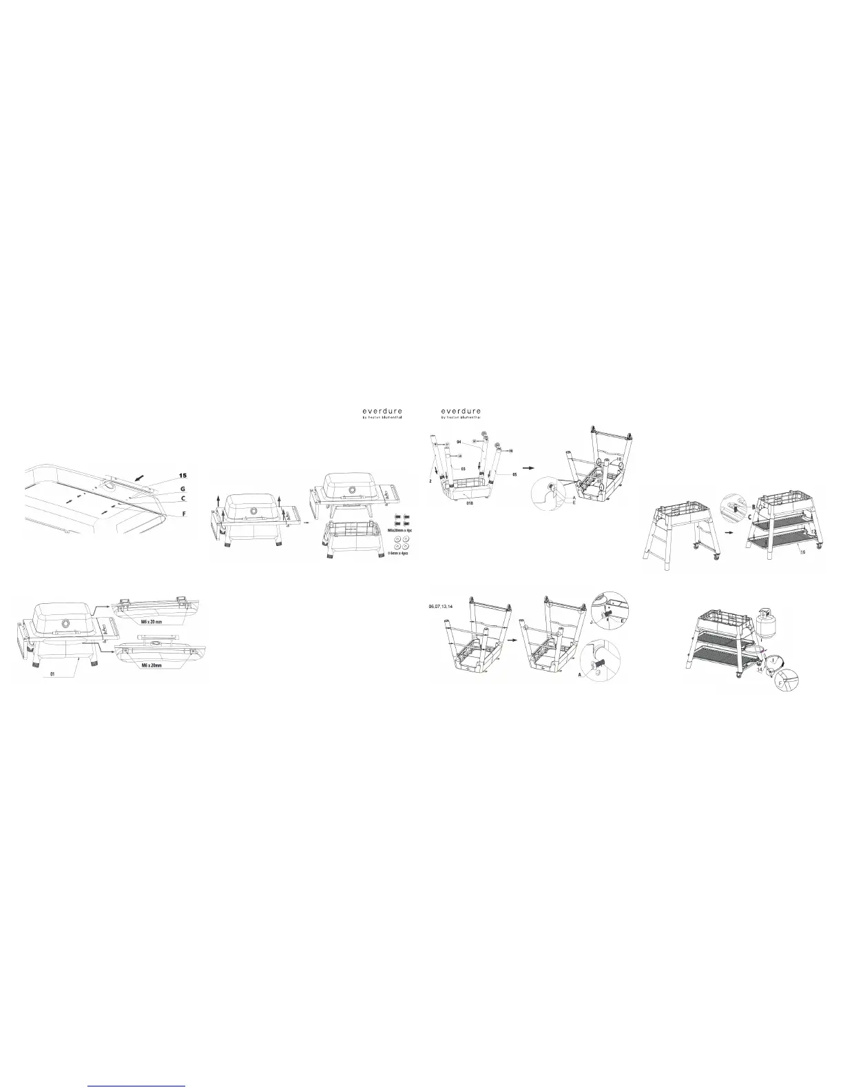
STEP 01
/Open the hood and x the hood handle (15) using two M5x0.6in (15mm) screws (F), two
Ø0.2in (5mm) spring washers (C) and two Ø0.2in(5mm) at washers (G). Tighten in place.
STEP 02
/ The hood and barbeque chassis assembly is transported screwed to the stand top by four
M6x0.8in (20mm) screws and four Ø0.2in (6mm) at washers (two at the front and two
at the rear). Before attempting to build the stand, the stand top should be removed.
Angle the assembly slightly to the back and remove both M6x0.8in (20mm) screws, then do the
same at the front, supporting the parts so they don’t drop. Keep all of the fasteners for later
use. Removable stickers at the front and rear will mark the positions of these screws.
Remove the hood and barbeque chassis assembly from the stand top and place on the ground.
STEP 03
/ Take the stand top (01B) and place it upside down (leg stumps up) on a clean surface (note:
there is no front or rear to this part).
Take the right front leg (04 with a screw hole in the foot) and slot it over the rear right corner
stump.
Take the right back leg (05 with a screw hole in the foot) and slot it over the front right corner
stump.
Take the left front leg (02) and slot it over the rear left leg stump.
Take the left back leg (03) and slot it over the front right leg stump.
Take the aluminium wire (18) and x them in the screw hole with four M6x0.5in (12mm) screw
(A) and at washer (E), but do not tighten.
STEP 04
/ Take the two bottom shelf supports (06.07) and t them onto the cylindrical tabs at the
inside of each foot. Rotate each one so that the outmost screw holes are facing inwards
and the inner screw holes are facing the stand top (if not, pull out and t in the opposite
way). Take the two upper shelf supports (13.14) and t them onto the legs (03.04.05.06).
Fix the bottom shelf support L (06) in place with two M6x0.5in (12mm) screws (A). Fix
the bottom shelf support R (07) in place with two M6x1in (28mm) screws (j) and at
washers (E). When all are assembled, tighten up all four screws and the screws from
step 03.
STEP 05
/ Turn the stand onto its legs and check that all of the legs are stable. Take the plastic bottom
shelf (16) and place it on the two bottom shelf supports. Line the four holes in the bottom
shelf up with the threaded holes in the bottom tray supports and x into position using four
M5x0.5in (12mm) screws (B) and four spring washers (C). Tighten fully. Take the plastic
upper shelf (17) and place it on the two upper shelf supports. Line the four holes in the upper
shelf up with the threaded holes in the upper tray supports and x into position using four
M5x0.5in (12mm) screws (B) and four spring washers (C). Tighten fully.
STEP 06
/ Take the cylinder belt (I) and x into place using two M5x0.6in (15mm) screw (F). The gas
cylinder can be put onto the bottom shelf support R (07) and x in place by cylinder belt (I).
Tighten it by adjusting the cylinder belt (I).