LT-101A User’s Manual
Copyright © EVERFINE, Copy or spread without authorization is prohibited.
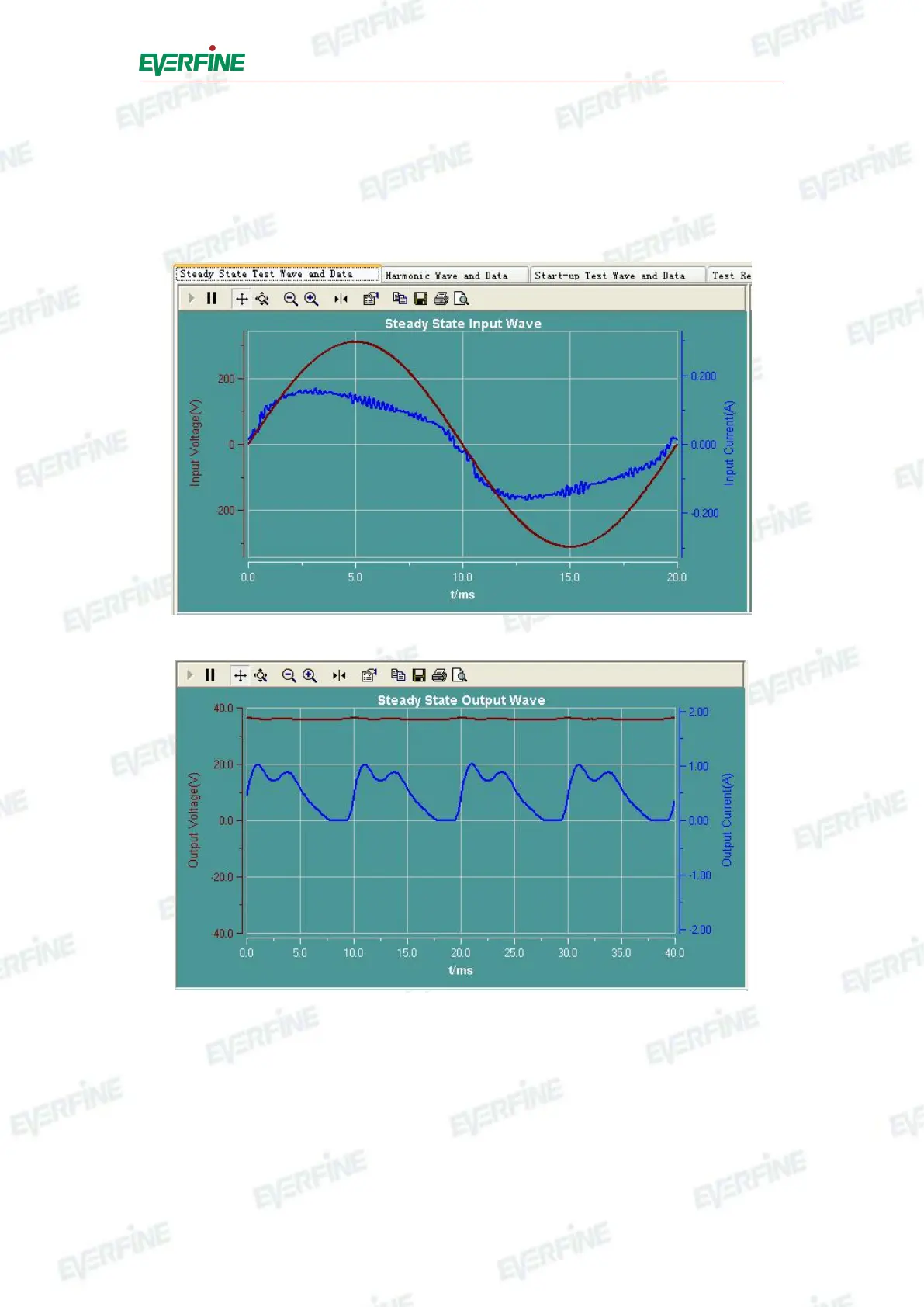
test, then users can see corresponding wave form data in coordinates at the bottom of
the interface. It will display the wave form of input/output voltage and current in
steady state test on the left, shown as Fig.6.7, and it will display the wave form of
input/output voltage and current in start-up test on the right, shown as Fig.6.8.
Fig.6.7-1 Input wave form in stability test
Fig.6.7-2 Output wave form in steady state test