4646
Helm Control Systems
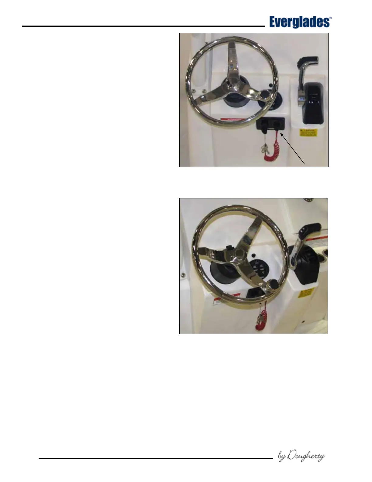
4.5 Engine Stop Switch
Your boat is equipped with an engine stop switch
and lanyard. When the lanyard is pulled it will
engage the switch and shut off the engine. We
strongly recommend that the lanyard be attached
to the driver whenever the engine is running. If
the engine will not start, it could be because the
lanyard is not properly inserted into the engine
stop switch. Always make sure the lanyard is
properly attached to the engine stop switch before
attempting to start the engine.
Refer to the engine owner’s manual for more in-
formation on the engine stop switch.
4.6 Steering System
Hydraulic Steering System
The steering system is hydraulic and made of two
main components: the helm assembly and the
hydraulic cylinder. The helm unit acts as both a
uid reservoir and pump. Turning of the helm or
steering wheel pumps the uid in the hydraulic
hoses and activates the hydraulic cylinder causing
the motor to turn. A slight clicking sound may
be heard as the wheel is turned. This sound is
the opening and closing of valves in the helm unit
and is normal.
Steering Cylinder
Single outboard engines are equipped with one
hydraulic steering cylinder mounted on the engine
that is connected directly to the engine tiller arm.
4.7 Trim Tabs
The trim tabs are mounted on the transom. A
dual rocker switch is used to control the trim tabs.
The switch controls bow up and down movements.
It also controls starboard and port up and down
movements. Bow up and bow down will control
the hull planing attitude, while port and starboard
up and down provides control for the hull listing.
Before leaving the dock or loading the boat on a
trailer or forklift, make sure that the tabs are in
the full “UP” position by holding the control in the
bow up position for ten (10) seconds.
LED Indicator Switch (Optional)
If your boat is equipped with the optional LED trim
indicator switch, red LED lights next to each switch
display the position of your trim tabs. Additionally,
the switch is wired so the trim tabs automatically
retract to the “full-up” position when the ignition
switch is turned off.
230 Center Console Engine Stop Switch
And Lanyard
Typical Helm
The LED display indicates trim tab deection.
When one LED indicator light is lit at the top of
each display, the tabs are in the “full-up” (bow up)
position. As the tabs are lowered (bow down) ad-
ditional indicator LED lights become lit to indicate
the degree of tab plane travel. When all LED lights
are lit, the tabs are fully extended (bow down).
 Loading...