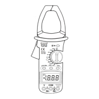
2. Press the trigger to open the transformer jaws and clamp
one conductor only it is impossible to make measurements
when two or three conductors are clamped at the same
time.
3. Display reading is flowing the conductor AC current.
6-3. Measure Resistance
1. Connect the BLACK test lead to the “COM” jack and the
RED to the“ ”jack (Note: The polarity of the red
test lead is positive “+”).
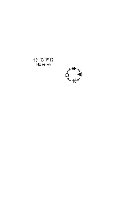
2. Set the function switch to range.
3. Press“RANGE” button can be select manually
measurement.
4. Press “SELECT” button to select resistance
measurement mode,the symbol “MΩ” will appear as an
indicator.
5. Connect the test leads across the load to be measured.
6. Read the reading on the display.
Note:
a. For resistance measurements >1MΩ, the meter may
take a few seconds to stabilize reading. This is normal
for high-resistance measurement.
b. When the input is not connected, i.e. at open circuit,
the symbol “OL” will be displayed as an over range
indicator.
c. Before measuring in-circuit resistance, be sure that
the circuit under test has all power removed and all
capacitors are fully discharged.
-12-