2. Make sure the polarity of the thermocouple is correct; put
the cold end (free end) of the thermocouple sensor into the
terminal (black to COM jack and red to “ ” jack).
3. Set the working end (testing end) on or inside the object
under test.
4. The value of the temperature is shown on the display in
degree centigrade (°C).
5. Press the “SELECT” button, fahrenheit and celsius can
be converted to each other.
6-7. Capacitance Measuring
1. Connect the BLACK test lead to the “COM” jack and the
RED to the “ ” jack.
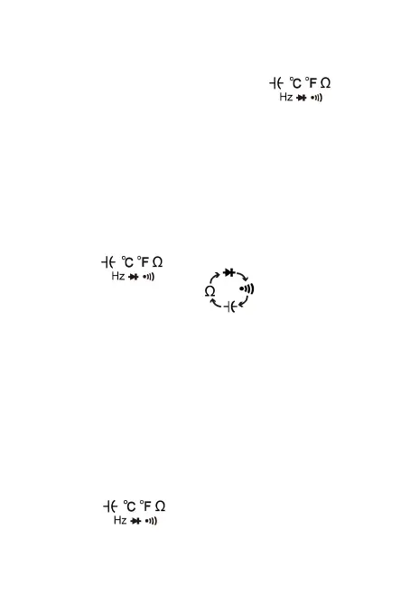
2. Set the function switch at “ ” position.
(NOTE: The polarity of the RED lead is positive “+”)
3. Connect test leads across the capacitor under measure
and be sure the polarity of connection is observed.
Note: When the capacitance under measure is above
100uF, it needs at least 5 second to make readings stable.
6-8. Frequency Measuring (auto range)
1. Set the function range switch to the required “Hz/DUTY”
position.
2. Connect the BLACK test lead to the “COM” jack and the
RED to the “ ” jack (Note: The polarity of the red
test lead is positive “+”).
3. Connect the test leads across the load to be measured.
-14-