6-4. Continuity Test
1. Connect the BLACK test lead to the “COM” jack and the
RED to the “ ” jack (Note: The polarity of the red
test lead is positive “+”).
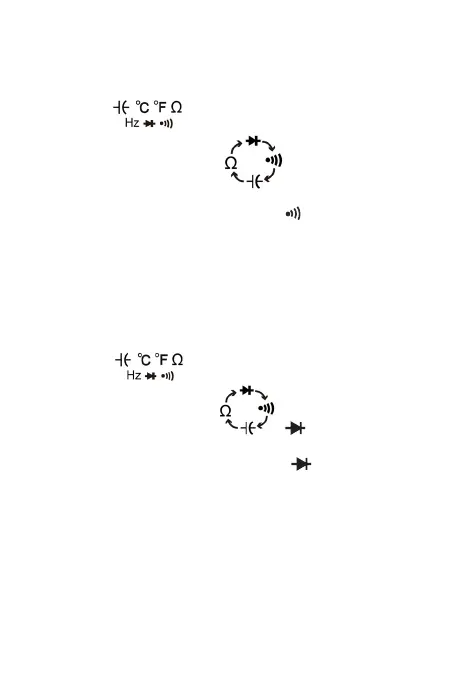
2. Set the function switch to “ ” range
3. Press the “SELECT” button to select continuity
measurement mode, and the symbol “ ” will appear as
an indicator.
4. Connect the test leads across the load to be measured.
5. If the circuit resistance is lower than about 30Ω, the
built-in buzzer will sound.
6-5. Diode Test
1. Connect the BLACK test lead to the “COM” jack and the
RED to the “ ” jack (Note: The polarity of the red
test lead is positive “+”).
2. Set the function switch to“ ” range
3. Press the “SELECT” button to select continuity
measurement mode, and the symbol “ ” will appear as
an indicator.
4. Connect the RED test lead to the anode of the diode to
be tested and the black test lead to the cathode.
5. The meter will show the approximate forward voltage of
the diode. If the connections are reversed, “OL” will be
shown on the display.
6-6. Measuring Temperature
1. Set the function range switch at the TEMP position.
-13-