- 12 -
Post Debug LED and LED Status Indicators
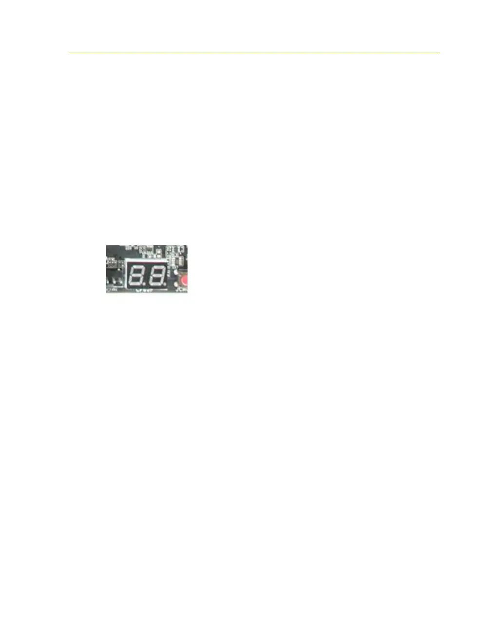
Post Port Debug LED
Provides two-digit diagnostic POST codes which shows system boot status and
can also show why the system may be failing to boot. It is very useful during
troubleshooting situations.
This Debug LED will display a series of hexadecimal (0-F) codes during the
POST and upon a successful boot, will display current CPU socket
temperatures after the system has fully booted into the Operating System. See
the “POST CODE” section below for more detailed descriptions of specific
POST Codes.
LED Status Indicators
Theses LEDs indicate the system’s status and are located near the 24pin
connector.
POWER LED (Green):
When the System is powered on: This LED is on.
DIMM LED (Yellow):
When the Memory slot is functional: This LED is on.
STANDBY LED (Blue):
When the System is in Standby Mode: This LED is on. This LED will
remain on as long as the motherboard is receiving constant power.
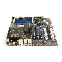
Debug LED with CPU
Temperature Monitor