EasyManuals Logo

EVGA Z97 User Manual

EVGA Z97
21 pages
To Next Page IconTo Next Page
To Previous Page IconTo Previous Page
Page #7 background imageLoading...
Page #7 background image
- 7 -
Connector
Pin
Signal
Pin
Signal
1
+3.3V
13
+3.3V
2
+3.3V
14
-12V
3
GND
15
GND
4
+5V
16
PS_ON
5
GND
17
GND
6
+5V
18
GND
7
GND
19
GND
8
PWROK
20
RSVD
9
+5V_AUX
21
+5V
10
+12V
22
+5V
11
+12V
23
+5V
12
+3.3V
24
GND
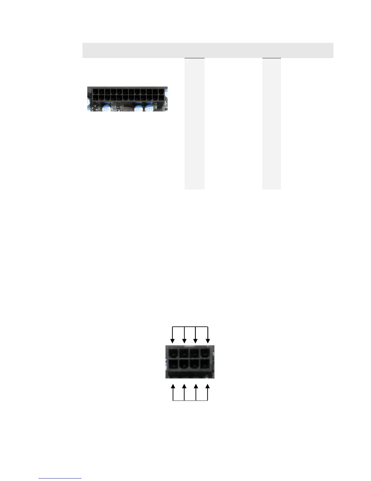
EPS 8-pin 12V Power (PWR 8P1)
EPS PWR 8P1, the 8-pin ATX 12V power connections, is used to provide
power to the CPU. Align the pins to the connector and press firmly until seated.
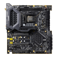
The secondary is optional for improved overclocking. Please remember to
make sure that the tab on the EPS socket is aligned with the release clip on the
cable, because if they are on opposite sides, while it will be able to fit, it is the
incorrect cable and may damage the board, as that is a PCI-E 8pin cable.
24
13
12
1
+12V

Other manuals for EVGA Z97

Questions and Answers:

Question and Answer IconNeed help?

Do you have a question about the EVGA Z97 and is the answer not in the manual?

EVGA Z97 Specifications

General IconGeneral
BrandEVGA
ModelZ97
CategoryMotherboard
LanguageEnglish

Related product manuals