PUMP FED - INSTALLATION
-5-
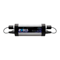
The C e tus whe n insta lle d a s a p ump fe d unit ,ne e d s
to ha ve the e xtra c o mp o ne nts (Fig ure s 1.4 a nd 1.5)
c o nne c te d a s in Fig ure 5.
This will e na b le a 1.5” (50mm) ha rd p ip e o r ho se ta il
fo r fl e xib le p ip e to b e fi tte d , c o nne c ting yo ur p ump
to the C e tus.
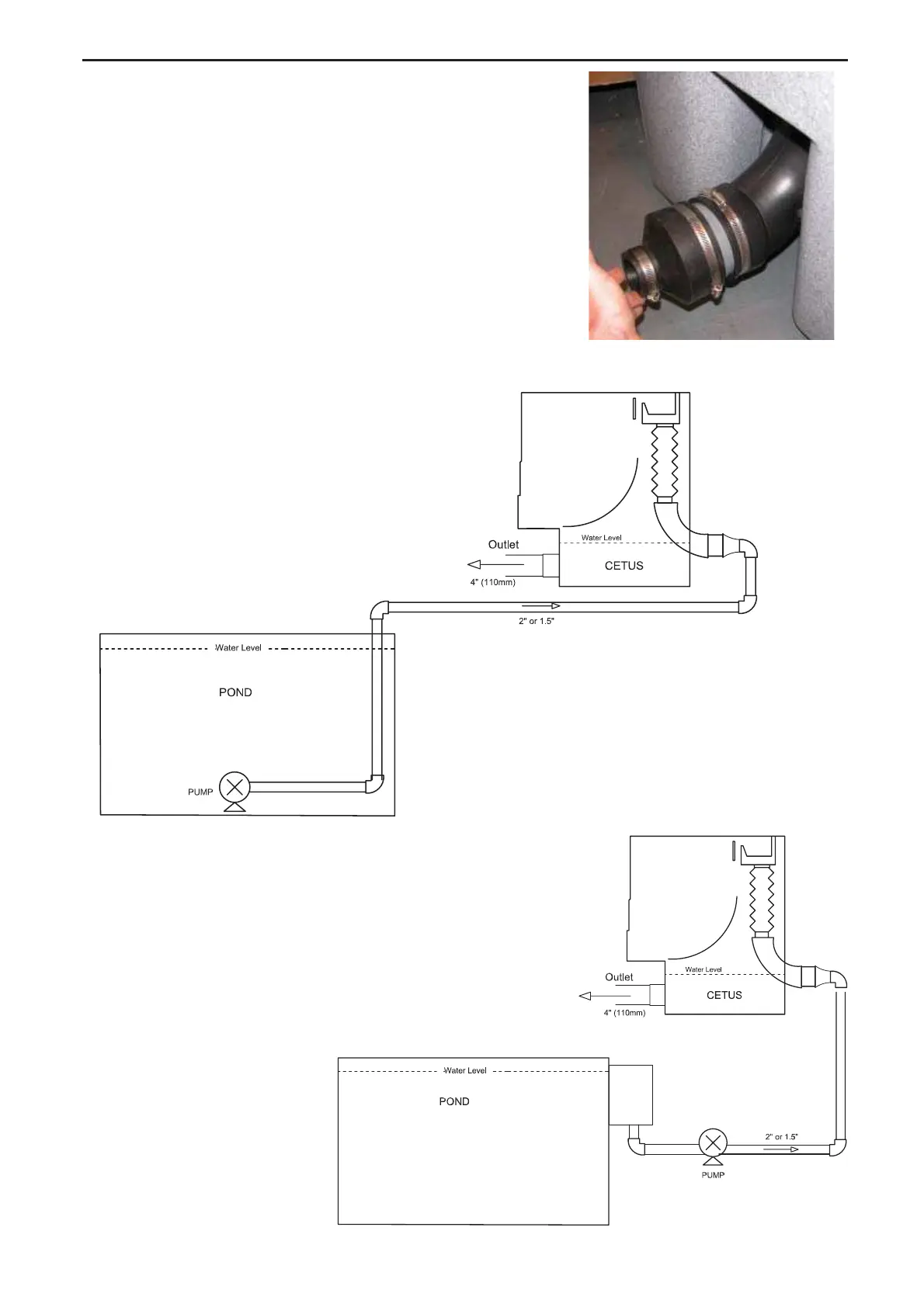
Whe n p ump fe d , the C e tus ne e d s to b e insta lle d
a b o ve wa te r le ve l a s sho wn in fi g ure 6 b e lo w.
Figure 6
Sideview of Pump Fed
Cetus Installation
Fig ure 6 sho ws the sta nd a rd
wa y o f insta lling a p ump fe d
C e tus.
While fi g ure 6a sho ws the
wa y o f insta lling a p ump fe d
C e tus o n a skimme r line .
Fig 6a
Fig 5