7
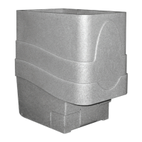
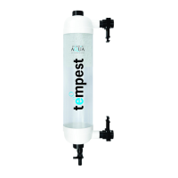
TEMPEST FILTER SET-UP
Follow these step by step instructions to set-up your Tempest filter ready for
installation.
STEP 1: Familiarise yourself with all the components from the parts bag.
STEP 2: At the bottom of the filter, screw on the waste valve assembly hand tight
only, do not use tools. (Ensure the o-ring is seated inside the screw cap)
STEP 3: Solvent weld one end of the 100mm length of 1½" connector pipe into the
inlet of the Tempest. Push pipe into the inlet until it stops.
STEP 4: Solvent weld the slide valve onto the opposite end of the 1½" connector
pipe. Push slide valve onto pipe until it stops.
STEP 5: Take the second 100mm length of 1½" connector pipe and solvent weld it
into the outlet of the Tempest filter. Push pipe into the outlet until it stops.
STEP 6: Solvent weld the slide valve onto the opposite end of the 1½" connector
pipe. Push slide valve onto pipe until it stops.
STEP 7: Allow the glue to set for atleast 5 hours.
The Tempest is now set-up ready for installation.
The slide valves fitted allow connection to 1½" pressure pipe.
If installing the Tempest Filter using flexible hose you will need to fit a reducing
sleeve (EA Code: M35-050) and a 1½" solvent stepped hosetail
(EA Code: HOSETAIL15) inside each slide valve.
IMPORTANT: Ensure the supplied o-ring is fitted inside the waste
valve assembly before screwing on to waste outlet.
ADVICE: We recommend having the slide valves face each other,
so the top valve points down and the bottom valve points up.