16
www.evolutionpowertools.com
WARNING: This machine must not be connected to a power
source until all assembly and preparation has been completed
and a safety check carried out. (<9.15)
ASSEMBLY
Remove the machine from the case and check that all
accessories are present and correct. Place the machine onto a
clean, sturdy work surface.
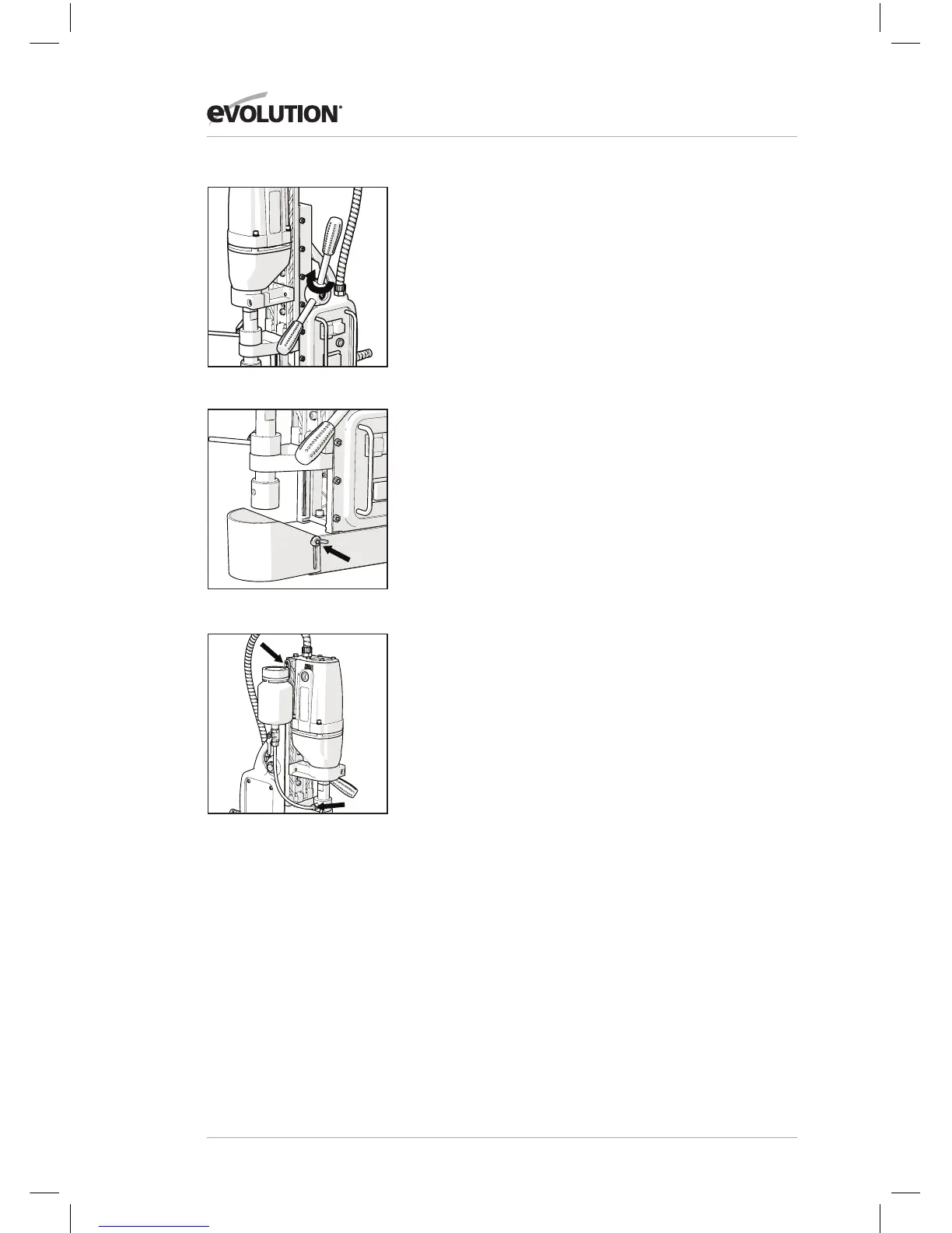
• Attach the three handles into the spindle hub ensuring that
they are fully seated. (Fig. 1)
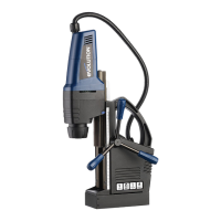
• Attach the Safety Guard and secure in place using the
supplied fixing screws. (Fig. 2)
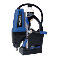
• Attach the coolant tank and coolant hose to the left hand
side of the machine. The coolant tube is a press fit into the
connector on the coolant inlet body. (Fig. 3b) The coolant
tank should be hung on the two protruding dome headed
screws located at the top left hand edge of the machine’s
main body. (Fig. 3a)
(9.16)
Note: To release the delivery tube from the quick connector,
push the collar towards the brass union and withdraw the
delivery tube.
(9.17)
Note: For some operations it may be convenient to remove
the coolant tank and supply tube, and to use alternative
coolant application methods.
>9.15 ASSEMBLY AND PREPARATION
FIG. 1
FIG. 3
FIG. 2
A
B