14
www.evolutionsteel.com
ASSEMBLY and PREPARATION
WARNING: This machine must not be connected to
a power source until all assembly and preparation has
been completed and a safety check carried out.
Assembly
Removethemachinefromthecaseandcheckthatallaccessories
are present and correct. Place the machine onto a clean, sturdy
work surface.
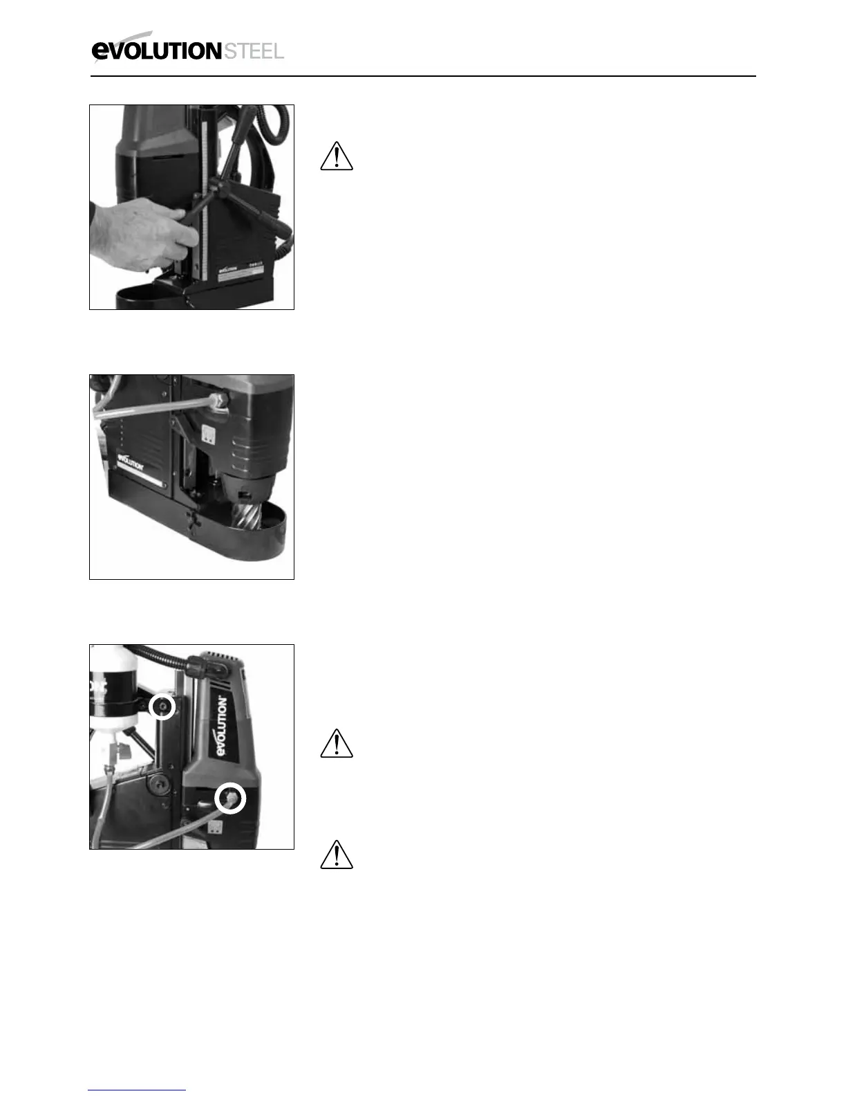
• Attachthethreehandlesintothespindlebossensuringthatthey
are screwed fully home. (Fig. 1)
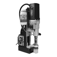
• AttachtheSafetyGuardandsecureinplaceusingthesupplied
fixing screws. (Fig. 2)
• Thecoolantsystemshouldbefastenedtothemachine
using the ø 6 mm (1/4”) socket headed screw inserted into
the threaded hole located at the top Left Hand side of the
machines carriage. (Fig. 3 a)
• Screwthelubricationquickconnectorintothethreadedhole
located just below the motor housing on the left hand side of
the machine. (Fig. 3b)
• Insertthefreeendofthedeliverypipeintothequickconnector.
Note: To release the delivery pipe from the quick connector push
the collar towards the brass union and withdraw the delivery pipe
Note: For some operations it may be convenient to remove
the coolant tank and supply pipe, and to use alternative coolant
application methods.
OPERATING INSTRUCTIONS
TESTING
WARNING: ThismachinehasCLASS1insulationand
MUST be earthed. Any power socket that this machine
is connected to must be grounded to earth. Ensure that both
operating switches are in the ‘OFF’ position before connecting the
power cord to the socket.
WARNING: The power cord assembly is a custom terminated
one.Replacementshouldonlybecarriedoutbyaqualied
technician. Only use replacement parts recommended by Evolution
Power Tools.
• Placethemachineontoapieceofclean10mmthickMildSteel
plate that is larger than the magnetic base of the machine.
• Connectthe13Aplugintoa13Amainssupplysocket(UK Only).
• Switchonthesocket.
Fig. 1
Fig. 2
Fig. 3
b
a