ASSEMBLY PROCEDURE
Select the Carriage Slide and Rotary Base and Bevel Neck.
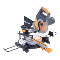
Fitting the Mitre Locking Handle
The threaded rod of the Mitre Locking Handle slides into a
tunnel, or screws into a boss (according to type of machine
purchased) located just above the Positive Stop Locking Lever.
Rotary Table Extension.
draw the Handle into the locking mechanism. (Fig. 3a)
Rotary Table.
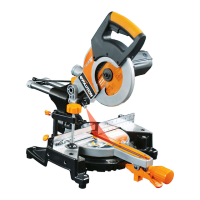
Fitting the Positive Stop Locking Lever
The Positive Stop Locking Lever pushes onto the lever
mechanism found just below the Mitre Locking Handle (Fig 3b)
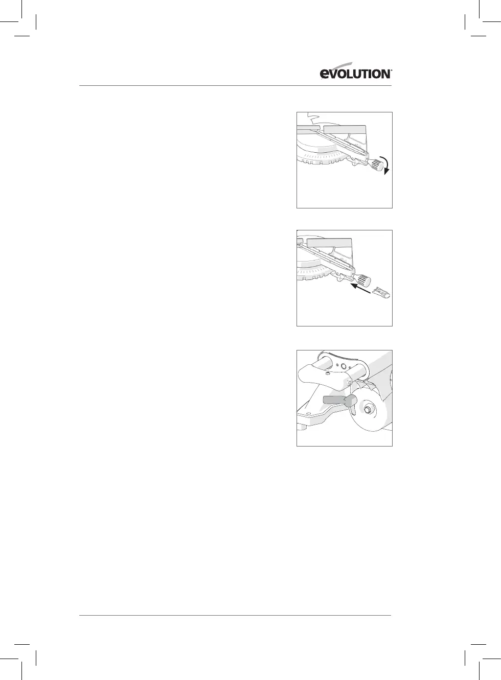
Adjusting the Bevel Neck to 0
0
The Bevel Neck is supplied fitted to the rotary base and tilted at a 45
0
angle to the left. Before the carriage slides are inserted into the Bevel
Neck, the Bevel Neck must be adjusted to the vertical position (0
0
).
(Fig. 4)
against the 0
0
stop.
Fig. 3a
Fig. 3b
Fig. 4
POSITIVE STOP
LOCKING LEVER
MITRE
LOCKING HANDLE
9
www.evolutionpowertools.com