2.2.LEDIndicators
LEDPositions
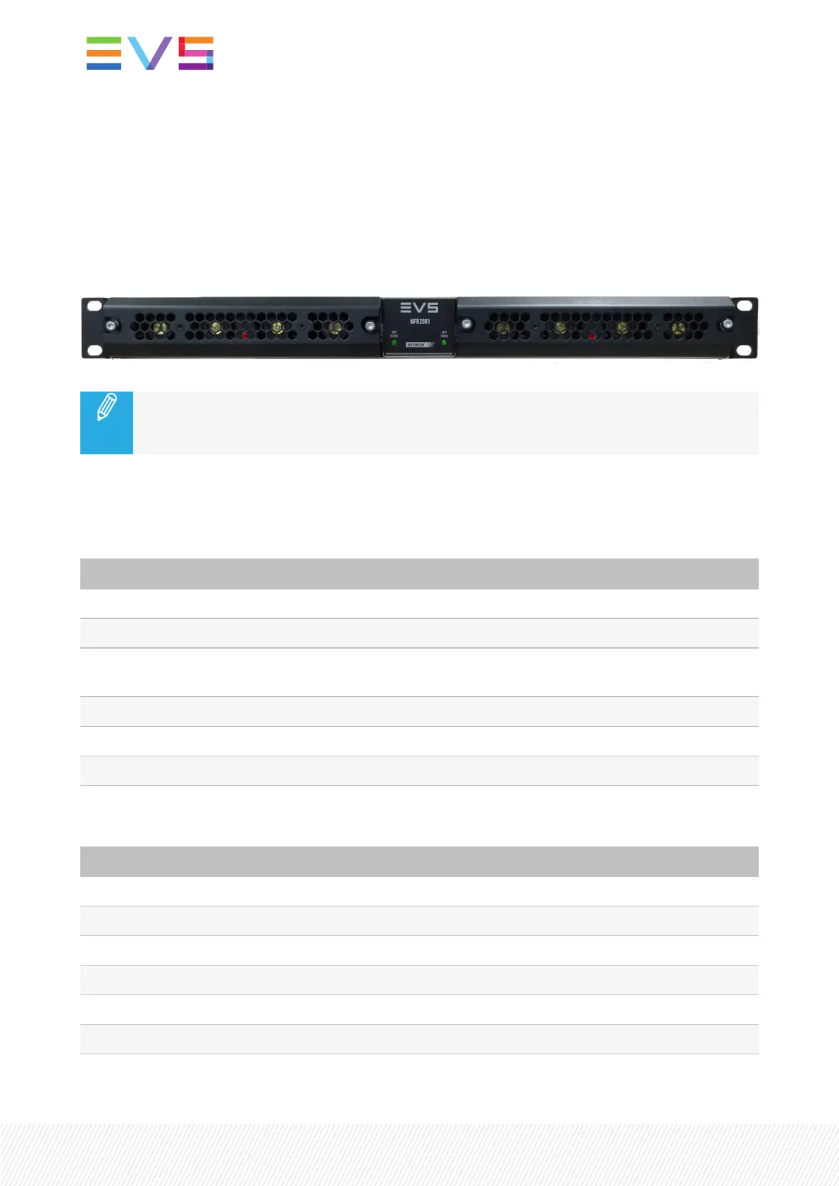
The NFR2001 frame has 4 LEDs: 1 for each power supply and 2 on the front plate. In the image below,
the PSU LEDs are indicated in red and the Front LEDs are in green:
The above image illustrates the broadcast version of the NFR2001 frame. On the datacenter
version, front-plate LEDs (in green) are also present on the unit, but the PSU LEDs are on the
back.
LEDFunctions
The following tables explain the meanings of the various indicators.
PSULEDs Description
Green constant Power present, controlled, no errors
Green blinking Power present, not controlled, no errors
Red constant No power present or DC/DC converter defect, controlled internal
communication error.
Red blinking No power present or DC/DC converter defect, or uncontrolled / fan error
Orange constant Fan override, controlled
Orange blinking Fan override, not controlled
Front Plate LEDs Description
Green constant Application running
Green blinking No application present, updating
Orange constant Booting
Orange blinking Warning, see menu for cause
Red blinking Error, see menu for cause
Green fast-blinking "Where am I?" function, manually triggered in the settings
6| March 2022 | Issue 4.1.E