Powerware
®
Plus 12 Operator's Manual (164200090 Rev E) $" !(4
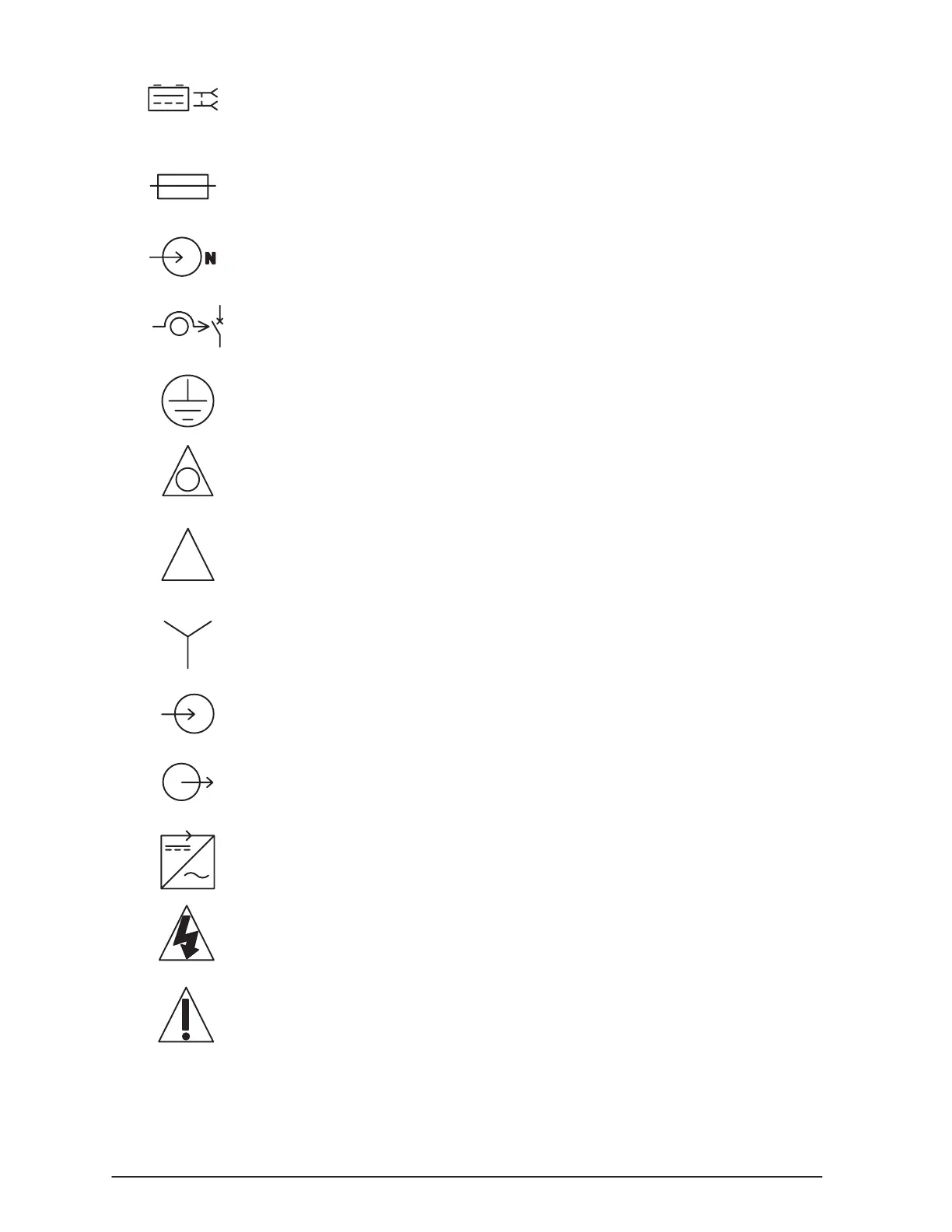
$$"( $ " indicates the 2Ćposition connector for battery
input.
%# indicates a fuse.
!%$ %$" %"$ '$ indicates the input neutral
configuration switch.
(!## #$ '$ indicates the bypass reset switches.
" % indicates the customer ground connections.
"( '") indicates an EPO switch or connection.
$ indicates the switch position for a delta (3-wire) input.
( indicates the switch position for a wye (4Ćwire) input.
!%$ indicates the input connections.
%$!%$ indicates the output connections.
&"$" indicates the inverter module.
# $" indicates that a risk of electric shock is
present and the associated warning should be observed.
%$ " !"$ "# % -Refer to your operator's
manual for additional information.