Powerware
®
Plus 12 Operator's Manual (164200090 Rev E) 15
3 UPS Operations
This chapter describes the UPS front panel control functions, UPS operating modes
and alarm conditions, and the Bypass and Emergency PowerĆOff features.
UPS Control Panel Functions
The front panel indicators illuminate only when one of the following conditions is
present:
Green when UPS is in Normal operating mode. If Bypass is enabled,
the Normal indicator flashes when Bypass is unavailable.
Yellow when UPS is in Bypass mode. The Bypass indicator flashes in
the event of a phase rotation (installation) alarm or loss of one phase.
Yellow when UPS is operating in the OnĆBattery mode. The Battery
indicator flashes when there is approximately two minutes or less of battery time
remaining. If the UPS is not operating on battery, this indicator flashes when the
UPS battery is disconnected (battery breaker open or battery disconnected).
Yellow when UPS is in an Overload condition.
NOTE: If all the indicators flash simultaneously, there is a problem with the UPS. Please
contact your field service representative.
The UPS automatically switches between Normal, OnĆBattery, and Bypass modes, as
required, with no operator intervention. Sophisticated detection and switching logic
ensures that any change in mode of operation is automatic and transparent to the load.
Operating Modes
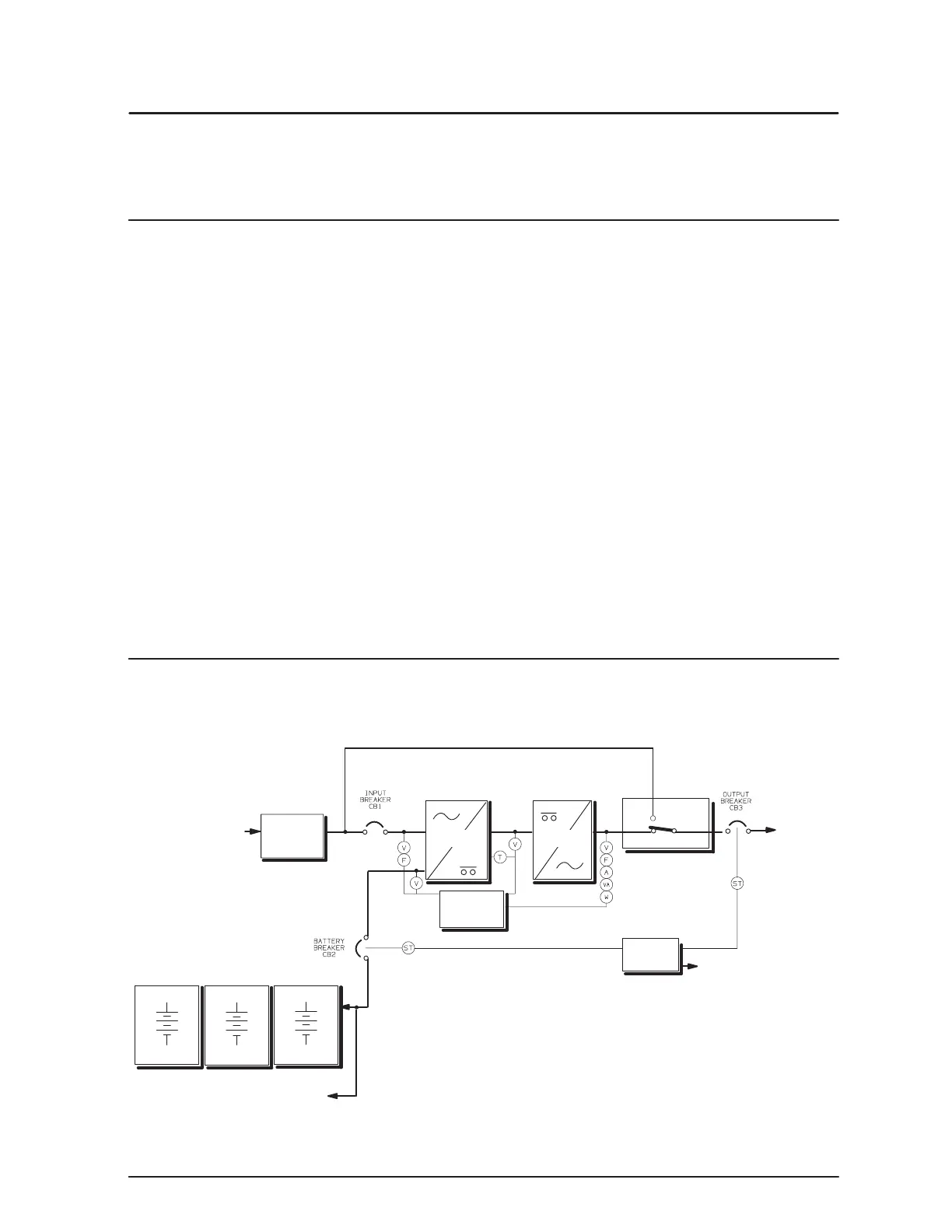
After you install and startup the Plus 12 UPS, the UPS filters and regulates incoming AC
power, eliminating noise and voltage spikes, and provides consistent power to your
equipment (see Figure 3).
AC
INPUT
TO UPS
SURGE
SUPPRESSION
EMI/RFI
FILTERS
FRONT
PANEL
BATTERY
RECTIFIER
INVERTER
BYPASS LINE
BATTERY CABINETS
AC OUTPUT
TO LOAD
TERMINAL BOARD
FOR REPO
REMOTE BATTERY
CONNECTION
BYPASS
PLUS
BATTERY
BATTERY
EMERGENCY
POWER
OFF
ST SHUNT TRIP
F FREQUENCY METER
A AM METER
V VOLT METER
VA VOLTĆAMP METER
W WATT METER
T TEMPERATURE
LEGEND
Figure 3. UPS Block Diagram