8 Installation
Powerware
®
Plus 12 Operator's Manual (164200090 Rev E) 44
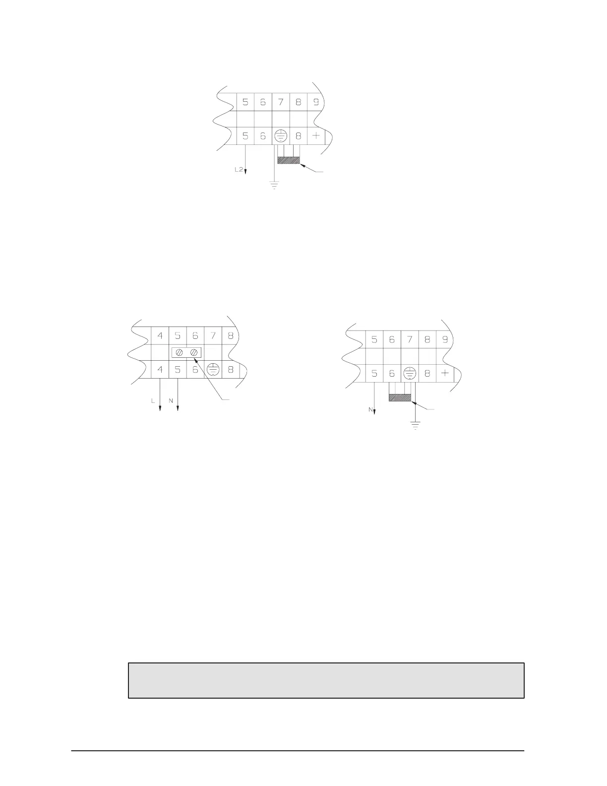
. Locate the grounding jumper between terminals 7 and 8 as shown in
Figure 17.
Grounding Jumper
Figure 17. Grounding Jumper
. The neutral conductor of the output circuit is bonded to the chassis/ground as
configured at the factory. If output neutral is not to be grounded, remove the
grounding jumper between terminals 7 and 8.
NOTE: It is recommended to remove the grounding jumper for threeĆwire delta
output.
. Locate the grounding jumper and the neutral bonding jumper (provided in a
bag located on the back of the unit).
Neutral Bonding
Jumper
Grounding
Jumper
Figure 18. Grounding and Neutral Jumper
. If input and output neutrals are to be bonded together (for IT and TT
installations), install the neutral bonding jumper between terminals 5 and 6.
. If output neutral is to be grounded (for TNS installation), install grounding
jumper between terminals 6 and 7.
. If you are using a Remote Emergency PowerĆOff switch, hardwire the terminal
block positions 14 and 15. See the termination table on page 43 for proper
connections.
The REPO switch is a customerĆsupplied switch that can disconnect the UPS
output voltage from your protected equipment. The REPO function activates when
the REPO wires are shorted together. Use the following specifications for the
REPO switch:
The switch should be a wallĆmounted, momentaryĆcontact, normally open,
pushbutton switch.
Minimum ratings of 120 VAC and 125 mA.
The REPO wires are at highĆvoltage potential (240V). Refer to your
local electrical code for proper installation of the highĆvoltage REPO wires.
. Replace the terminal block plate and the conduit plate on the UPS rear panel.
. Continue to the following section, Final Configuration."
 Loading...