4-27
Charging System Specifications
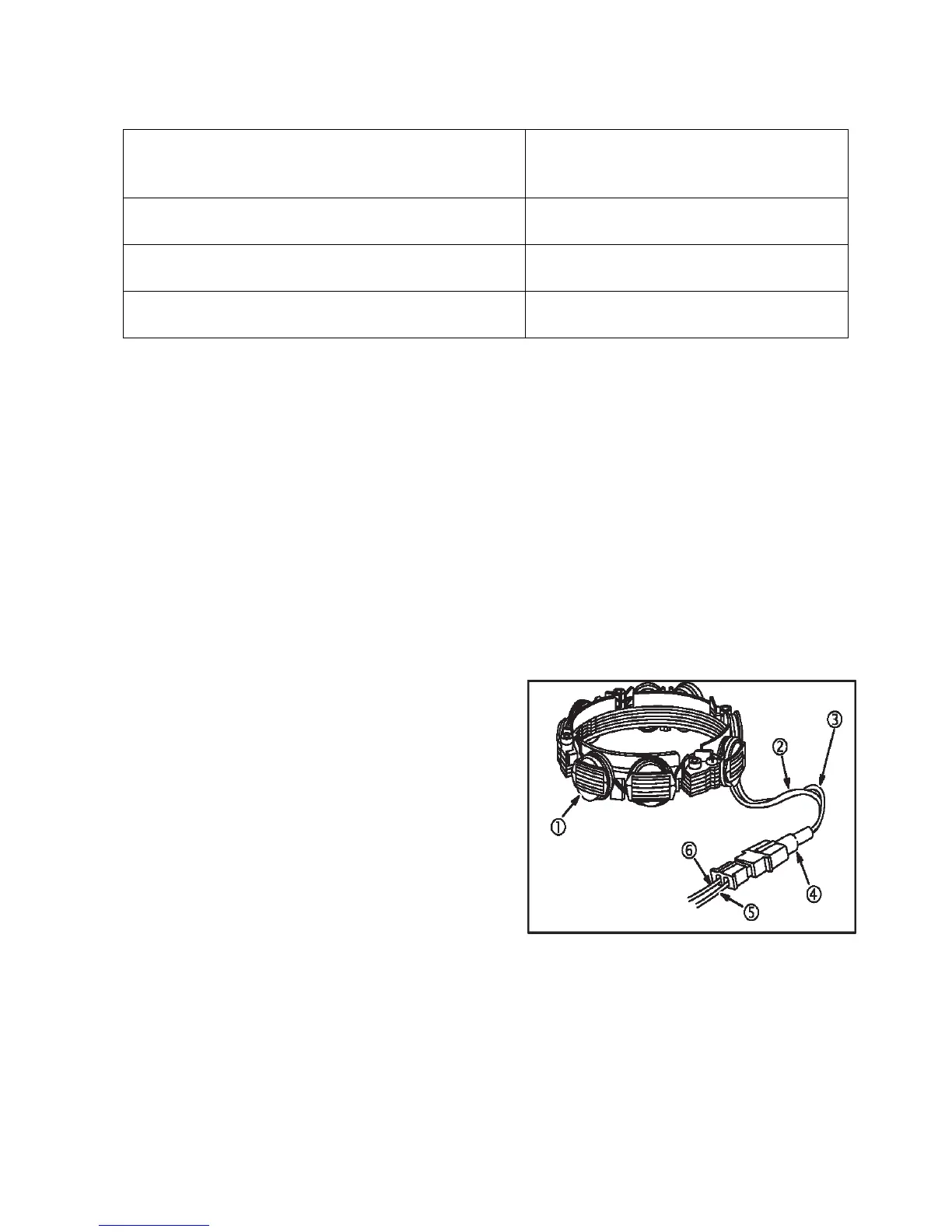
AC Output Test
1. Insert
RE
D
test
lead
into
VC
receptacle
in meter.
2.
Insert BLACK
test lead into COM receptacle.
3. Rotate selector to
V-
(AC
VOLTS)
position.
4. Attach RED test lead clip (1) to AC output terminal(5),
Fig.18.
5. Attach BLACK test lead clip (2) to engine ground.
6. With engine
running
at 3600 RPM output should be no less than 14 volts
AC.
7. NOTE: The battery MUST be in good condition to
perform
this test.
Charge Coil(s) Air Gap
Measure Between the Magnet Area of the Flywheel and the
Charge Coil Legs
No Load DC Voltage Output @ 3000 RPM
Measure Across Battery Terminals
No Load AC Voltage Output @ 3000 RPM
Measure Across Stator Leads – Stator Leads Disconnected
Charge Coil / Stator Resistance
Measure Resistance Across the Two Stator Leads