4.8 Analog Output Wiring
Analog outputs are optional. Analog outputs are available across the same terminals that
are used for the relay outputs. See Control Relay terminals table above. Parameter ‘Ct’ (PID
Menu 3) must be set to ‘0’ when using an analog output.
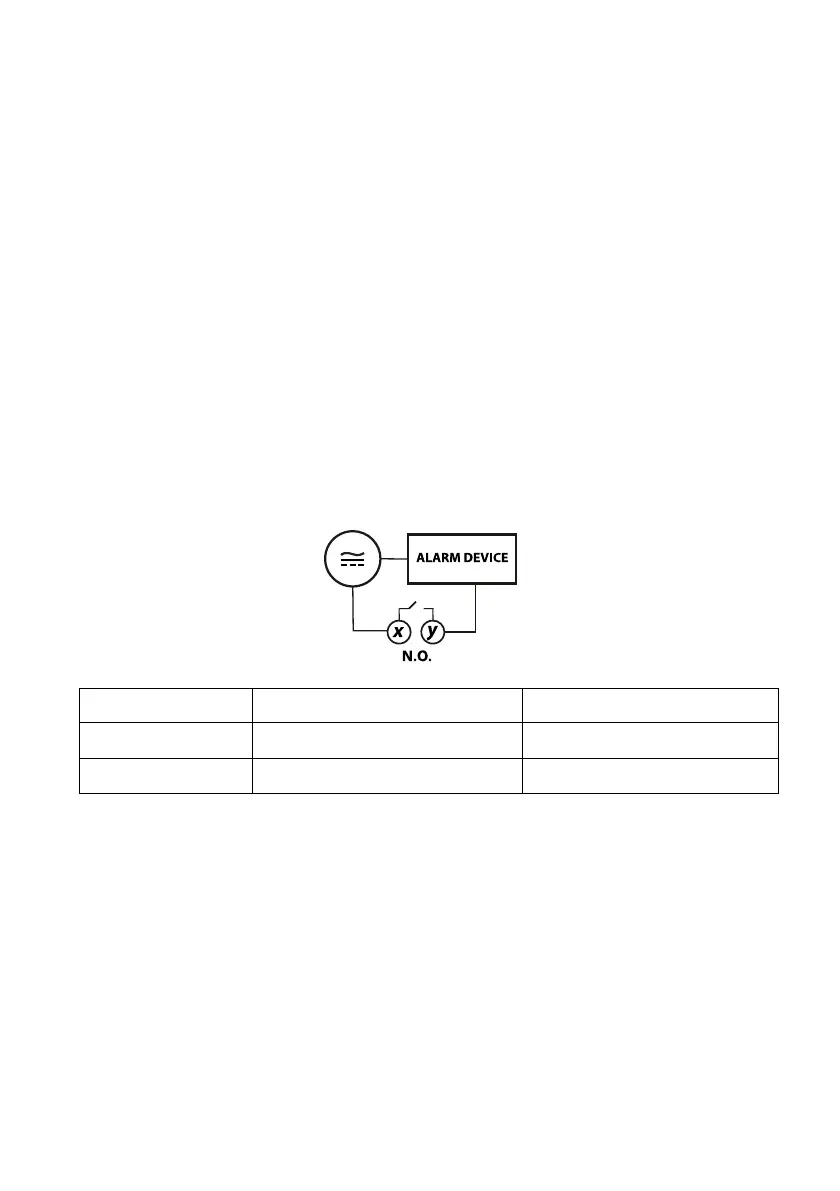
4.9 Alarm Relay Output
One relay is supplied in a standard VFL controller, the second alarm is optional. Alarm relays
are normally open (N.O.) single-pole single-throw mechanical switches. The first alarm relay
is available on terminals 11 and 12. The optional secondary alarm relay is on terminals 12
and 13.
Alarm relays do not supply power and should be wired in series with power and the alarm
device.
Alarm relays are rated 3 Amps @ 110VAC or 24VDC (Resistive Loads).
In the diagram below terminals ‘x’ and ‘y’ represent the VFL rear terminal designations, see
the table below for the specific terminal numbers.
FIGURE 4.3 - NORMALLY OPEN (N.O.) ALARM WIRING