MN25 Version 2.2 Aug 2003
12
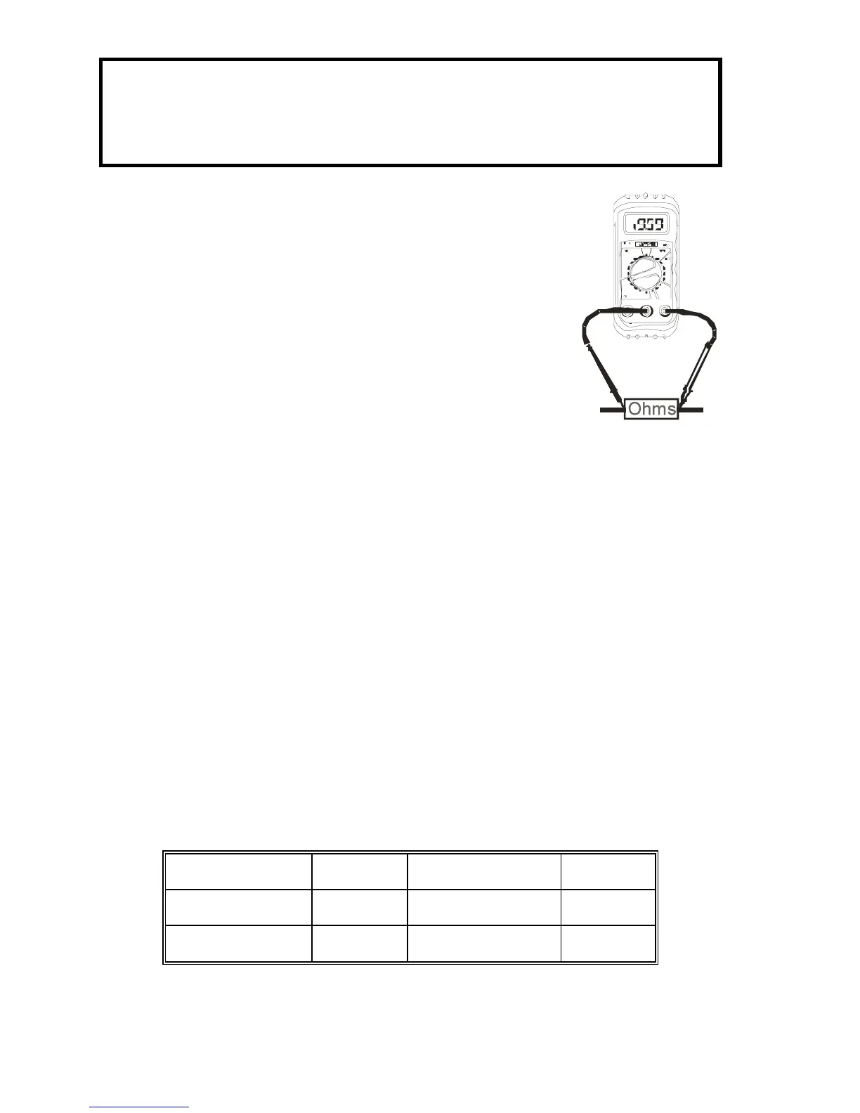
Resistance Measurements
WARNING: To avoid electric shock, disconnect power to the
unit under test and discharge all capacitors before taking any
resistance measurements. Remove the batteries and unplug
the line cords.
1. Set the function switch to the highest Ω
position.
2. Insert the black test lead banana plug into
the negative (COM) jack
Insert the red test lead banana plug into
the positive Ω jack.
3. Touch the test probe tips across the circuit
or part under test. It is best to disconnect
one side of the part under test so the rest
of the circuit will not interfere with the resistance reading.
4. Read the resistance in the display and then set the function
switch to the lowest Ω position that is greater than the actual
or any anticipated resistance. The display will indicate the
proper decimal point and value.
Battery Test
1. Insert the black test lead banana plug into the negative COM
jack and the red test lead banana plug into the positive V
jack.
2. Select the 1.5V or 9V BAT position using the function select
switch.
3. Connect the red test lead to the positive side of the 1.5V or
9V battery and the black test lead to the negative side of the
1.5V or 9V battery.
4. Read the voltage in the display.
Good Weak Bad
9V battery: >8.2V 7.2 to 8.2V <7.2V
1.5V battery: >1.35V 1.22 to 1.35V <1.22V