Do you have a question about the Extech Instruments MiniTec Series and is the answer not in the manual?
Explains symbols indicating potential hazards or references to the manual for safety.
Lists critical safety rules for operating the multimeter to prevent injury or damage.
Identifies and describes the main parts of the multimeter, including display and jacks.
Defines symbols used on the multimeter and in its manual, such as units and test types.
Step-by-step guide for measuring AC and DC voltage using the multimeter.
Instructions for safely measuring DC current, including range selection and precautions.
Procedures for performing resistance measurements with the multimeter.
How to conduct continuity tests and interpret the results, including audible feedback.
Advises on keeping the meter dry, clean, and handling it gently for longevity.
Table detailing function ranges, resolutions, and accuracy specifications.
Specifies the maximum voltage and current inputs allowed for each function.
Covers diode test, continuity, impedance, bandwidth, display, and battery indicators.
Details operating/storage conditions, humidity, altitude, weight, size, and certifications.
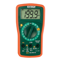
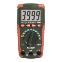
The Extech MiniTec™ Series MultiMeter, Model MN24, is a professional-grade multimeter designed to measure AC/DC Voltage, DC Current, Resistance, Battery Voltage, Diode Voltage, and Continuity. This device is shipped fully tested and calibrated, ensuring reliable service with proper care.
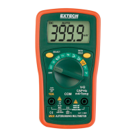
The MN24 multimeter features an LCD display for clear readings. Its primary functions are selected via a rotary switch. The device includes dedicated jacks for COM (common), 10A current measurements, and a positive jack for voltage, resistance, and milliampere measurements.
Voltage Measurements (AC or DC): To measure AC or DC voltage, the black test lead banana plug is inserted into the negative COM jack, and the red test lead banana plug into the positive V jack. The rotary switch is then set to the desired VDC or VAC range. The test probes are touched to the circuit under test, and the voltage reading appears on the display.
DC Current Measurements: For DC current measurements, the black test lead banana plug goes into the negative COM jack. The red test lead banana plug is inserted into either the positive mA jack for currents up to 200mA or the positive 10A jack for currents up to 10A. The rotary switch is set to the appropriate ADC range. The test probes are connected in series with the circuit under test to read the current. A caution is noted for 10A scale measurements: they should not exceed 30 seconds to prevent damage to the meter or test leads, with a 15-minute cool-down period recommended after high current measurements.
Resistance Measurements: To measure resistance, the black test lead banana plug is inserted into the negative COM jack, and the red test lead banana plug into the positive Ω jack. The rotary switch is set to the desired Ω range. The test probes are touched to the circuit or device under test, and the resistance is displayed.
Continuity Measurements: For continuity checks, the test leads are connected as for resistance measurements (black to COM, red to Ω). The rotary switch is set to the continuity position (•))). When the test probes touch a circuit or device, a buzzer will sound if the resistance is less than approximately 30Ω, and the resistance value will be displayed.
Diode Measurements: Diode measurements involve inserting the black test lead banana plug into the negative COM jack and the red test lead banana plug into the positive diode jack. The rotary switch is set to the diode/continuity position. When the test probes touch the diode under test, a forward voltage of 400 to 700mV will be indicated. A reverse voltage will show "I". Shorted devices will indicate near 0mV, while an open device will show "I" in both polarities.
Battery Test: To test batteries, the black test lead banana plug is inserted into the negative COM jack, and the red test lead banana plug into the positive V jack. The function select switch is set to either the 1.5V or 9V BAT position. The red test lead is connected to the positive side of the battery, and the black test lead to the negative side. The voltage reading is then displayed.
DC Voltage (V DC):
AC Voltage (V AC):
DC Current (A DC):
Resistance (Ω):
Battery Test:
Diode Test:
Continuity Check:
General Specifications:
The MN24 Multimeter is designed for dependable service, emphasizing safety and ease of maintenance for its users.
| Category | Multimeter |
|---|---|
| Model | MiniTec Series |
| DC Voltage (Max) | 600V |
| AC Voltage (Max) | 600V |
| DC Current (Max) | 10A |
| AC Current (Max) | 10A |
| Continuity | Yes |
| Diode Test | Yes |
| Display | LCD |
| Battery Type | 9V |
| Auto Power Off | Yes |
| Low Battery Indicator | Yes |
| Safety Rating | CAT III 600V |