EXTEL - WAVE - 720313
en - 2
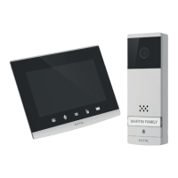
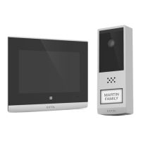
A - KIT CONTENTS
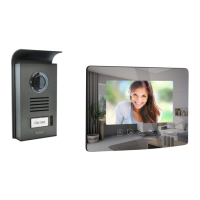
B - DESCRIPTION OF MONITOR
1 Monitor
2 Intercom panel
3 Surface mounting bracket
4 Antenna
5 Plug
6
Fixing screws for monitor bracket and surface
mounting bracket
1 7" colour screen
2 Microphone
3
Screen off: Intercom panel preview (surveillance
mode, only when the intercom panel is not battery-
powered)
Menu: left arrow or up arrow
Call in progress: takes a photo
4
During communication: Starts/ends a call
In surveillance mode: initiates
communication
Menu: right arrow or down arrow
5
Screen off: Enables touch keys and access
to the time and then the menu by pressing
again
Menu: OK (selection button).
Call in progress: Access the image settings
7
Hexagonal screwdriver 1.5mm
8 Plug-in power supply for the screen
9 PowerBox
10 Flat cable (1 m)
11 Additional power supply for the PowerBox
6
In call or surveillance mode:
Opening of the
electric strike plate (only when the intercom
panel is not battery-powered)
7
In call or surveillance mode: Opens dry
contact (gate motor drive)
Menu: Back/Exit (back button to parent
menu)
8 Loudspeaker
9 Jack connector for powering
10 SD memory card slot (8GB, included)
11
QR code to identify the doorkeeper
12
Antenna
Fig. 1
Fig. 2
C - DESCRIPTION OF THE
INTERCOM PANEL
1 Protective case
2 Camera and infrared LEDs
3 Loudspeaker
4
Name holder (the transparent plastic can be peeled
back to write on the label)
5 Microphone
6 Call button
7
Dawn-to-dusk cell capable of detecting
ambient brightness
8
Connectors for the PowerBox
1 Antenna
2 Battery compartment (4 x LR20, not included)
3 Pairing button (red)
4
Reset button (black)
5
Connectors for power supply, strike plate and
motor drive
6 Connectors for the intercom panel
7 Eco mode management switch
Fig. 3 Fig. 4
D - DESCRIPTION OF
THE POWERBOX