Do you have a question about the FAAC 610MPS and is the answer not in the manual?
Essential safety rules and precautions for installers to prevent harm from incorrect installation or misuse.
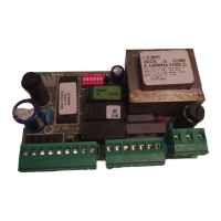
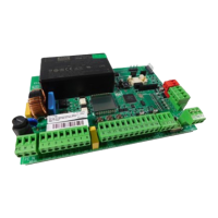
Details operating parameters and hardware characteristics for 596MPS and 610MPS models.
Diagram and overview of electrical connections for the 596MPS model with failsafe enabled.
Diagram and overview of electrical connections for the 610MPS model with failsafe enabled.
Detailed description of low voltage terminal board J1 connections for commands and safety devices.
Description of high voltage terminal board J2 connections for capacitor and electric motors.
Explanation of J3 connector for rapid connection of accessory cards like MINIDEC, DECODER, RP RECEIVER.
Details on J4 connector for rapid connection of the opening push-button on up-and-over operators.
Description of J9 terminal board for connecting the 230V~50Hz main power supply.
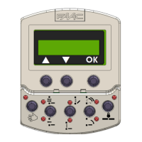
Configuration of automatic/semi-automatic logic, pause time, and opening/closing times via microswitches.
Explains behaviours of automatic (A) and semi-automatic (E) logics for system operation.
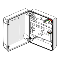
Instructions for initial installation and system start-up, including rotation direction check.
Examples of connecting safety devices (edge, photocells) when failsafe is disabled.
Examples of connecting safety devices (edge, photocells) when failsafe is enabled.
| Programmable Inputs | 4 |
|---|---|
| Programmable Outputs | 2 |
| Number of Outputs | 2 |
| Operating Temperature | -20°C ÷ +55°C |
| Protection Fuses | 2A |