Do you have a question about the FAAC E024U and is the answer not in the manual?
Details the main power supply, operating temperature, protection fuses, and motor parameters.
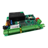
Identifies key components on the control board, including connectors and indicators.
Explains how to connect RP and RP2 radio receivers to the board.
Describes the function of various input terminals like 2EASY, OPEN A, STOP, and safety inputs.
Details the function of output terminals such as LAMP, LOCK, and motor outputs.
Provides instructions for connecting N.O. photocell contacts in parallel.
Provides instructions for connecting N.C. photocell contacts in series.
Explains photocell placement for protecting specific gate movement areas.
Diagram for connecting two pairs of closing photocells.
Diagram for connecting mixed closing and opening/closing photocells.
Diagram for connecting two pairs of opening photocells.
Wiring diagram for systems without safety or stop devices (not recommended).
Diagram for connecting generic closing and opening safety devices.
Configuration of DIP switches for various operating logic modes like Semiautomatic, Automatic, and Security.
Trimmers for adjusting motor force, speed, and obstacle detection sensitivity.
Trimmers for setting pause time and leaf 1 over leaf 2 closing delay.
Configuration for opening delay, reverse on last stroke, and max thrust at startup.
Settings for automatic opening on power failure, closing safety logic, and preflashing.
Settings for obstacle detection sensitivity, terminal functions, and lamp/warning lamp outputs.
DIP switch settings to select the type of gate operator (e.g., S450H, S418).
Configuration for the lock output mode, either timed or always active.
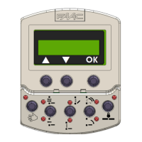
Description of LED indicators for power, setup, error, bus communication, and USB status.
LEDs indicating the status of inputs like OPEN A, STOP, and limit switches.
Table correlating LED flashes to specific error conditions and their solutions.
Procedure for automatic learning of gate movement times and slowdown points.
Step-by-step guide for manual learning of gate movement and slowdown points.
Explanation of how obstacle detection works and its behavior during gate movement.
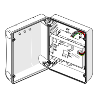
Details the dimensions of the enclosure that fits the E024U board panel.
Diagram showing placement of control board, power supply, and accessories.
Instructions for safe AC power connection, including wiring and breaker recommendations.
Guidance on connecting a 24V backup battery for power failure operation.
Instructions on how to disable the battery charger function by unplugging jumper J24.
Steps for upgrading the board's firmware using a USB flash drive.
Defines system status and command behavior for Logic E (Semiautomatic).
Defines system status and command behavior for Logic A (Automatic).
Defines system status and command behavior for Logic S (Security).
Defines system status and command behavior for Logic EP (Semiautomatic step by step).
Defines system status and command behavior for Logic AP (Automatic step by step).
Defines system status and command behavior for Logic SP (Security step by step).
Defines system status and command behavior for Logic B (Manned Pulsed).
Defines system status and command behavior for Logic C (Manned Constant).
| Manufacturer | FAAC |
|---|---|
| Category | Controller |
| Model | E024U |
| Max Output Current | 2A |
| Operating Temperature | -20°C to +55°C |
| Protection Class/Degree | IP54 |