FSW
STP CL OP
FSW
STP CL OP
Connection of two pairs of closing photocells
Connection of a pair of closing photocells, a pair of opening photcells and a pair of opening/closing photocells
Other optional safety devices to connect in series
Fig. A7
Fig. A8
To use the FAIL-SAFE
mode connect the nega-
tive power supply of the
transmitters to OUT (pin 9),
and set dip-switch 11 and
12 to ON on DS1
When using the FAIL-
SAFE mode also the safety
inputs not used (FSW CL,
FSW OP) must be con-
nected to OUT (pin No. 9)
To use the FAIL-SAFE
mode connect the nega-
tive power supply of the
transmitters to OUT (pin
9), and set dip-switch 11
and 12 to ON on DS1
RX= Photocell Receiver
TX= Ptotocell Transmitter
CL= Closing
OP= Opening
RX= Photocell Receiver
TX= Ptotocell Transmitter
CL= Closing
OP= Opening
A5
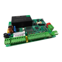
E024U CONTROL BOARD