Do you have a question about the FAAC 615 BPR and is the answer not in the manual?
Essential safety precautions before operating the equipment.
Details on power requirements, motor capacity, and accessory current limits.
Specifies operating temperature range and fuse ratings for protection.
Configuration options for operational modes and time delays.
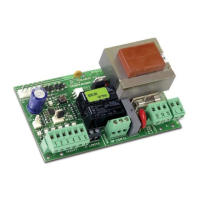
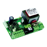
Overview of the control unit's physical layout and key components.
Detailed descriptions of each terminal board connector and component.
Illustrates the wiring diagram and connection points for external devices.
Details specific device connections for each terminal board number.
Step-by-step guide to selecting operational logic modes using the SW1 button.
Table detailing logic types and their corresponding SW1 button presses.
Explains the meaning of LED indicators for system status.
Guide for the automated learning process of operational and pause times.
Instructions to enable or disable the pre-flashing safety function for motor starts.
Procedure to verify correct operation, especially safety device functionality.
Details operation for logic B/C, outlining status and actions.
Details operation for logic AP, outlining status and actions.
Details operation for logic B, outlining status and actions.
Details operation for logic P, outlining status and actions.
Details operation for logic C, outlining status and actions.
Details operation for logic A, outlining status and actions.
Details operation for logic EP, outlining status and actions.
Compliance declaration with relevant safety and EMC directives.
The FAAC 596/615 BPR control unit is a versatile electronic device designed to manage automated systems, particularly for barriers or up-and-over doors. Its primary function is to control the opening and closing operations, integrating various safety and command inputs to ensure reliable and secure operation.
The control unit operates by interpreting signals from various inputs and activating corresponding outputs to control the motor and other ancillary devices. It supports multiple operating logics, allowing for flexible configuration based on specific application requirements. These logics include:
The unit manages motor operation, including opening and closing stages, and provides outputs for a flashing light (LAMP) to signal movement and a courtesy light (COURT.) for illumination. It also handles inputs from various safety devices, such as photocells (SAFE), and limit switches (FCA for opening, FCC for closing) to ensure safe operation and prevent damage. The control unit can learn the work time (the duration of motor operation for a full cycle) and pause time, adapting to the specific gate or barrier dimensions and desired operational delays.
The 596/615 BPR is designed for ease of setup and configuration. Programming the function logic is done via a single SW1 push-button, where a specific number of presses corresponds to a desired logic. The selected logic is then indicated by the DL1 LED, which flashes a certain number of times.
Time learning is a crucial feature, allowing the unit to automatically determine the optimal work time for opening and closing. This process involves manually guiding the system through a full cycle while the unit records the necessary motor run times. For systems with limit switches, the unit automatically stops when the switch is engaged. If limit switches are not installed, the unit relies solely on the learned work time. The pause time, particularly relevant for automatic logics (A or AP), is also learned in a similar fashion, allowing the user to set the desired duration the gate remains open before automatically closing.
The control unit includes a pre-flashing function, which can be activated to make the flashing lamp go on three seconds before the gate starts moving, enhancing safety by providing an early warning. This feature can be enabled or disabled through a simple procedure involving the SW1 button and the STOP contact.
Diagnostic LEDs (DL1, OP-A, CLOSE, SAFE, STOP, FCA, FCC) provide real-time status feedback for inputs and operational states, simplifying troubleshooting. For instance, the SAFE LED indicates the status of safety devices, while FCA and FCC LEDs show whether the opening and closing limit switches are free or engaged.
The unit supports connection of an RP2 type 2-channel radio receiver to the J2 connector, enabling remote control of both OPEN and CLOSE functions. If a single-channel RP type receiver is used, only the OPEN command can be controlled.
Before any maintenance or work on the electronic equipment, it is imperative to turn off the power to ensure safety. The unit is protected by fuses: F1 for motor protection and F2 for accessories protection. F2 is self-resetting, indicating a level of self-recovery for minor accessory overloads.
The modular design, with clearly labeled terminal boards (J1, J2, J3, J4, J6, J7, J8, J9), facilitates easy connection and disconnection of components. The presence of diagnostic LEDs (DL1, OP-A, CLOSE, SAFE, STOP, FCA, FCC) is a significant maintenance aid, allowing technicians to quickly identify the status of inputs and operational states without complex diagnostic tools. This helps in pinpointing issues such as a triggered safety device, an engaged limit switch, or a command input problem.
The ability to learn work time and pause time means that if a motor or mechanical component is replaced, the unit can be re-calibrated to the new system without extensive manual adjustments. The clear distinction between power cables and control/safety cables, along with the recommendation for separate sheaths or screened cables, helps in preventing electrical disturbances, which can be a common source of intermittent faults and difficult-to-diagnose issues. This design consideration contributes to the overall reliability and ease of maintenance by reducing potential interference.
| Model | 615 BPR |
|---|---|
| Category | Control Unit |
| Operating Temperature | -20 °C to +55 °C |
| Weight | 1.5 kg |
| Power Supply | 230 V AC |
| Protection Class | Class I |
| Protection Degree | IP54 |