EasyManua.ls Logo

FAAC 860 User Manual

FAAC 860
27 pages
To Next Page IconTo Next Page
Page #1 background imageLoading...
Page #1 background image
The 820/860 Slide Gate
Operator: Installation Manual
Contents
Important Safety Information........................................................................2
Technical Data ..............................................................................................4
Unpacking the Operator ................................................................................5
The 820/860 Slide Gate Operator..................................................................6
General Characteristics .............................................................................6
Operating Logic ........................................................................................7
Manual Release Mechanism..................................................................7
E1 (Semi-Automatic 1) Mode ...............................................................8
E2 (Semi-Automatic 2) Mode ...............................................................8
A1 (Automatic 1) Mode ........................................................................8
A2 (Automatic 2) Mode ........................................................................9
S1 (Security) Mode ...............................................................................9
S2 (Security Plus) Mode .......................................................................9
B Mode..................................................................................................9
C Mode..................................................................................................9
Installation Instructions...............................................................................11
Set the Forms for the Conduit and Concrete ..........................................11
Ground Mounting................................................................................11
Cantilevered Mounting........................................................................11
Mount the Operator on the Foundation Plate .........................................11
Chain Operator ....................................................................................11
Rack and Pinion Operator ...................................................................12
Connect the Electrical Power .................................................................14
Set the DIP Switches...............................................................................15
Operating Logic...................................................................................16
Pause Time ..........................................................................................16
Warning Light Operation ....................................................................17
Gate Orientation ..................................................................................17
Set the Limit Switches.............................................................................17
Define the Midpoint ............................................................................18
Set the Opened Limit...........................................................................19
Set the Closed Limit............................................................................19
Relocating the Midpoint......................................................................19
Install Other Accessories.........................................................................20
Remove the Bleed Screw ........................................................................21
Adjust the Clutch of the Operator ...........................................................22
Maintenance ................................................................................................23
Troubleshooting ..........................................................................................24
Exploded View, 820/860 Mechanical Parts ................................................25
Exploded View, 820/860 Electronic Parts ..................................................26
FAAC International, Inc.
303 Lexington Avenue
Cheyenne, WY 82007
www.faacusa.com

Other manuals for FAAC 860

Question and Answer IconNeed help?

Do you have a question about the FAAC 860 and is the answer not in the manual?

FAAC 860 Specifications

General IconGeneral
Opening Speed12 m/min
Operating Temperature-20°C to +55°C
Protection Class/RatingIP44
Model860
TypeGate Opener
Power Supply230V AC
Safety FeaturesObstacle detection

Summary

Important Safety Information

Gate Design Safety

Discusses safety considerations for gate design and placement.

Installation Safety Practices

Emphasizes safety during installation and consulting the manufacturer.

Equipment Usage Guidelines

Covers general usage guidelines and precautions for the equipment.

The 820/860 Slide Gate Operator

General Characteristics

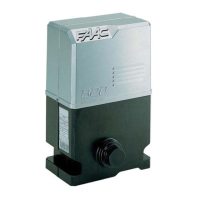
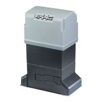
Describes the features and design of the 820/860 operators.

Operating Logic

Manual Release Mechanism

Explains the emergency release mechanism for manual gate operation.

E1 Semi-Automatic Mode

Details the E1 operating logic for semi-automatic gate control.

E2 Semi-Automatic Mode

Details the E2 operating logic, similar to E1 with differences in reversing device response.

A1 Automatic Mode

Details the A1 operating logic for automatic gate opening and closing.

A2 Automatic Mode

Details the A2 operating logic for automatic gate control with specific reversing device responses.

S1 Security Mode

Details the S1 security mode, similar to A1 with immediate closing on signals.

S2 Security Plus Mode

Details the S2 security plus mode, with specific handling of reversing devices during pause.

B Mode Operation

Details the B mode, requiring manual button presses for gate movement.

C Mode Operation

Details the C mode, where the gate moves only while the button is pressed.

Installation Instructions

Conduit and Concrete Forms

Instructions for preparing concrete forms for the gate operator installation.

Ground Mounting

Specific steps for ground mounting the operator's foundation.

Cantilevered Mounting

Guidelines for cantilevered gate installations and pedestal requirements.

Mount Operator on Foundation Plate

Steps to mount the operator onto the prepared foundation plate.

Chain Operator Installation

Installation steps for the chain drive operator.

Rack and Pinion Operator Installation

Installation steps for the rack and pinion drive operator.

Connect Electrical Power

Instructions for connecting the main power supply to the operator.

Set DIP Switches

Guide to setting the DIP switches for operator logic and functions.

Set Operating Logic

Details how to set the operating logic using DIP switches S1, S2, S3.

Set Pause Time

Details how to set the pause time using DIP switches S4, S5.

Warning Light Operation

Explains how to configure the warning light using DIP switches S6, S7.

Gate Orientation

How to set the gate orientation using DIP switch S8.

Define Gate Midpoint

Procedure for defining the gate leaf's midpoint position.

Set Opened Limit Switch

Steps to set the limit switch for the fully opened gate position.

Set Closed Limit Switch

Steps to set the limit switch for the fully closed gate position.

Relocate Midpoint

Instructions for relocating the gate leaf's midpoint when necessary.

Install Other Accessories

Terminal Wiring for Accessories

Describes terminal connections for various accessories like reversing devices.

Warning Light Wiring

Details wiring for warning lights using terminals 8, 9, and 10.

High Voltage Connections

Explains high-voltage power supply terminals and main power source connections.

Entrapment Protection

Recommends installing photocells for entrapment protection.

Remove the Bleed Screw

Adjust the Clutch of the Operator

Maintenance

Check Oil Level

How to check the oil level in the operator.

Change Operator Oil

Procedure for draining and refilling the operator's oil.

Check Clutch Adjustment

Recommended frequency for checking clutch adjustment.

Troubleshooting

Normal LED Status Indicators

Table showing normal LED status for gate conditions.

Gate Fails to Open

Troubleshooting steps for when the gate fails to open.

Gate Fails to Close

Troubleshooting steps for when the gate fails to close.

Partial Gate Closing Issue

Troubleshooting for partial closing issues, potentially related to DIP switch S8.

Incomplete Gate Travel

Troubleshooting steps for incomplete gate travel.

Exploded View: Mechanical Parts

Exploded View: Electronic Parts

Limited Warranty

Related product manuals