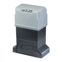
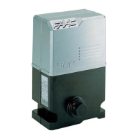
The FAAC Model 844 is an electromechanical operator designed for sliding gates. It transmits motion to the sliding gate leaf via a rack or chain pinion, which is appropriately coupled to the gate. This system ensures that the gate is mechanically locked when the motor is not operating, eliminating the need for an additional lock.
The gearmotor of the 844 operator is equipped with a mechanical clutch. This clutch, combined with an electronic device, provides adjustable anti-crushing safety, which helps to stop or reverse the gate's movement if an obstacle is detected. In the event of a power cut or malfunction, a manual release mechanism allows the gate to be moved manually. The control board, if supplied with the gearmotor, is housed inside the operator.
The 844 automated system is specifically designed and manufactured to control access for vehicles. It is not intended for any other purpose.
Users are advised to read and follow all instructions carefully. Children should never be allowed to operate or play with the gate controls, and remote controls should be kept away from them. People and objects must always be kept clear of the gate, and no one should cross the path of a moving gate.
The gate operator should be tested monthly. It is crucial that the gate reverses on contact with a rigid object or when a non-contact sensor is activated. If necessary, the force or limit of travel should be adjusted, and the gate operator retested. Failure to properly adjust and retest the gate operator can increase the risk of injury or death. The manual release mechanism should only be used when the gate is not moving. Proper gate maintenance is essential, and a qualified service person should perform any necessary repairs to the gate hardware. The entrance is intended for vehicles only; pedestrians must use a separate entrance. These instructions should be saved for future reference.
Important Installation Instructions:
The gate operator should only be installed if the gate is appropriate for its type and usage class. All openings of a horizontal slide gate must be guarded or screened from the bottom of the gate to a minimum of 6 feet (1.83 m) above the ground. This prevents a 2-1/4 inch (57.2 mm) diameter sphere from passing through openings in the gate or the adjacent fence when the gate is in the open position. All exposed pinch points must be eliminated or guarded, and guarding must be supplied for exposed rollers.
The operator is intended for installation on gates used by vehicles only; pedestrians must be provided with a separate access opening. To reduce the risk of entrapment during opening and closing, the gate must be installed in a location that allows adequate clearance between the gate and adjacent structures. Swinging gates must not open outward into public access areas. Before installing the gate operator, ensure that the gate is properly installed and swings freely in both directions. The operator clutch or pressure relief valve should not be over-tightened to compensate for a damaged gate.
Controls for user activation must be located at least six feet (6') away from any moving part of the gate, preventing the user from reaching over, under, around, or through the gate to operate the controls. Emergency access controls, accessible only by authorized personnel (e.g., fire, police, EMS), may be placed at any location in the line-of-sight of the gate. Stop and/or Reset buttons must be located within line-of-sight of the gate, and activation of the reset control should not cause the operator to start. All warning signs and placards must be installed and easily visible within proximity of the gate, with a minimum of one warning sign on each side.
For gate operators utilizing a non-contact sensor (e.g., a photo beam), refer to specific instructions for sensor placement. Care should be taken to reduce nuisance tripping, such as when a vehicle trips the sensor while the gate is still moving. One or more non-contact sensors should be located where the risk of entrapment or obstruction exists, such as at the reachable perimeter of a moving gate or barrier. Only FAAC "Photobeam" photoelectric eyes should be used to comply with UL325.
For gate operators utilizing a contact sensor (edge sensor or similar), one or more contact sensors should be located where the risk of entrapment or obstruction exists. This includes at the leading edge, trailing edge, and post-mounted both inside and outside of a vehicular horizontal slide gate. For vehicular vertical lift gates, sensors should be at the bottom edge. For vertical barriers (arms), sensors should be at the bottom edge. For vehicular vertical pivot gates, sensors should be at the pinch point. Hard-wired contact sensors and wiring should be routed to prevent mechanical damage to communication between the sensor and gate operator. Wireless contact sensors, which transmit radio frequency (RF) signals, should be located where signal transmission is not obstructed or impeded by building structures, natural landscaping, or similar hindrances. Wireless contact sensors must function under their intended end-use conditions. Only FAAC XS 55, CN 60 E edge sensors should be used.
General Safety Precautions:
Vehicular gates should be constructed and installed in accordance with ASTM F2200: Standard Specification for Automated Vehicular Gate Construction. If there are questions or concerns regarding the safety of the gate operating system, the operator should not be installed, and the manufacturer should be consulted. The reliability and safety of the gate operator are directly affected by the condition of the gate structure itself. Only qualified personnel should install this equipment; failure to meet this requirement could result in severe injury and/or death, for which the manufacturer cannot be held responsible. The installer must provide a main power switch that meets all applicable safety regulations. It is extremely unsafe to compensate for a damaged gate by increasing hydraulic pressure. Devices such as reversing edges and photo beams should be installed to provide better protection for personal property and pedestrians, choosing devices appropriate to the gate design and application. Before applying electrical power, ensure that the voltage requirements of the equipment correspond to the supply voltage, referring to the label on the gate operator system.
Usage:
This equipment should only be used for its designed capacity. Any other use is considered improper and dangerous. The manufacturer is not responsible for damage caused by improper, erroneous, or unreasonable use. If a gate system component malfunctions, the main power should be disconnected before attempting repairs. The movement of the gate should not be impeded, as this may result in injury or damage to the gate system. The equipment may reach high thermal temperatures during normal operation, so caution should be exercised when touching the external housing. The manual release mechanism should be used according to the procedures in this manual. Before performing any cleaning or maintenance, power to the equipment must be disconnected. All cleaning, maintenance, or repair work must be performed by qualified personnel.
Installing Warning Signs:
The FAAC slide gate operator comes with two warning signs to alert people to potential hazards and necessary precautions. One warning sign must be permanently installed on each side of the gate, fully visible to traffic and pedestrians. Appropriate hardware, such as metal screws (not supplied), should be used for permanent installation.
Mechanical Installation:
The mounting brackets and anti-vibration spacers should be assembled on the operator. The cover should be opened by removing the securing screws. The operator should then be attached to the plate using the supplied washers and nuts, routing cables through the opening inside the lower half-casing. The height and distance from the gate should be adjusted, and the operator secured to the foundation plate by tightening the nuts. To access the electronic board, cables should be routed through the appropriate hole using the supplied rubber cable-clamp, ensuring the jacket is stripped on all cables so the clamp holds single cables only.
Installing the Rack:
For steel racks to be welded, three threaded dowel nuts should be placed on the rack element, positioned at the top of the slot to allow for adjustments. The gate leaf should be manually moved to its closed position. The first piece of rack should be laid level on the pinion, and the threaded dowel nut welded to the gate. The gate should then be moved manually to check that the rack is resting on the pinion, and the second and third dowel nuts welded. Subsequent rack elements should be placed next to the previous one, using a third piece of rack to synchronize the teeth of the first two elements. The gate should be moved manually, and the three threaded dowel nuts welded, continuing until the gate is fully covered.
For steel racks to be screwed, the gate leaf should be manually moved to its closed position. The first piece of rack should be laid level on the pinion, with a spacer between the rack and the gate, positioned at the top of the slot. The drilling point on the gate should be marked, a Ø 1½ inch hole drilled, and a Ø 5/16 inch male tap applied. The bolt should then be screwed in. The gate should be moved manually to check that the rack is resting on the pinion, and this step repeated.
Notes on Rack Installation:
Ensure that no rack elements derail from the pinion during gate travel. Rack elements should not be welded to the spacers or to each other. After installation, the gearmotor position should be lowered by about 1/16 inch to ensure correct meshing with the pinion. Manually check that the gate regularly reaches the mechanical stop limits and that there is no friction during gate travel. Grease or other lubricants should not be used between the rack and pinion.
Installation of Chain Pinions:
Operators for chain and idle transmissions require the installation of a Z16 or Z20 chain pinion. For Model 844 ER CAT, the pin should be inserted on the shaft using a hammer. The chain pinion should be fitted on the shaft, aligning the channel with the pin, and the screw and appropriate washers tightened. For Model 844 ER RF, the pin should be inserted on the shaft using a hammer. The idle transmissions bracket should be fitted on the operator flange using four screws and appropriate washers. The chain pinion should be fitted on the shaft, aligning the channel with the pin, and the screw and appropriate washers tightened. The chain should be passed as shown, and the cover installed with a screw and washer.
Limit Switches:
For operators with magnetic limit switches, a bracket must be provided to mount them on the gate, following the specified distances.
Mechanical Clutch Adjustment:
The 844 operator includes a mechanical clutch in addition to its electronic safety devices (encoder and force adjustment). In typical applications, the clutch does not need adjustment as it is factory-set to its maximum strength. For adjusting the operator's thrust and reversing behavior, the force and encoder settings detailed in the programming sections should be used. If clutch adjustment is necessary, electrical power to the operator should be cut. The motor shaft should be locked with a wrench, and the clutch adjustment screw turned with an Allen wrench or screwdriver. Turning clockwise increases torque, while turning counter-clockwise reduces it. After adjustment, power should be restored, and the torque checked. The operator is supplied with a clutch adjustment spring for gates up to 2200 lbs; for heavier gates, an alternative spring is supplied.
Final Operations:
After installation, the danger sticker should be applied to the top of the cover. The side panels should be snapped into place, the equipment cover installed, and secured with the supplied screws. The vent screw should be removed.
Manual Operation:
In case of a power outage or malfunction, the gate can be operated manually. To do this, open the protection door, insert the supplied key into the lock, turn the key clockwise, and pull the release lever. The gate can then be opened and closed manually.
Restoring Normal Operation:
To prevent an involuntary pulse from activating the gate, power to the system should be cut before re-locking the operator. Re-close the release lever, turn the key counter-clockwise, remove the key, and close the lock protection door. Move the gate until the release engages.
Maintenance:
The operational efficiency of the system, especially the safety and release devices (including operator thrust force), should be checked at least once every six months.
To disassemble the transformer-board unit, remove all terminal boards and connectors from the board. Unscrew the three screws from the board and the two from the transformer. Lift the unit up and gently remove the transformer from the couplings on the board.
Oil Top-Offs:
The oil level inside the operator should be checked periodically. A once-a-year check is sufficient for medium or low usage, but for heavy-duty usage, a check every six months is recommended. To access the tank, temporarily remove the plastic oil filler cap. The oil level should visually cover the copper coil of the electric motor. If more oil is needed, it should be added through the oil filler hole. Only FAAC HP oil should be used.
Repairs:
For any repairs, an FAAC authorized repair center should be contacted.