2
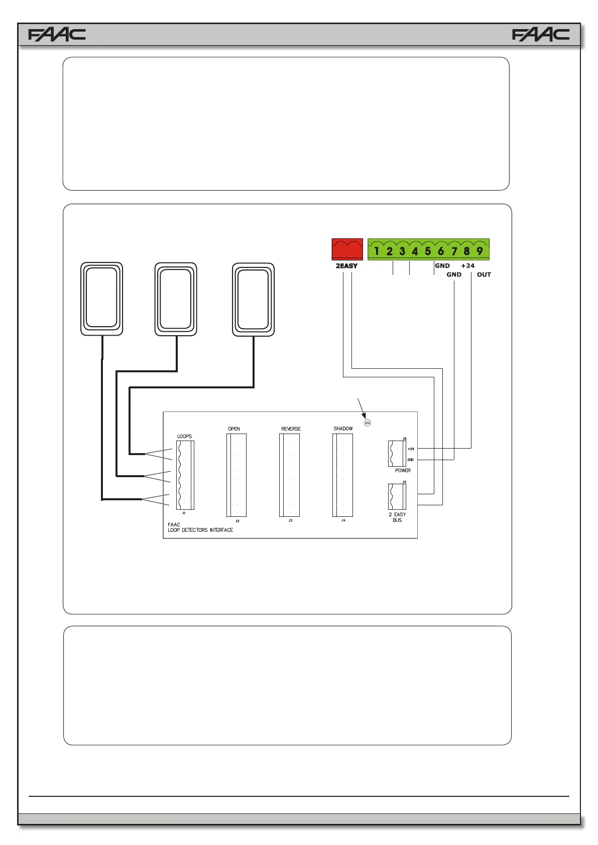
The 2670.1 loop detector interface allows to connect up to three plug-in detectors associ-
ated with standard functions. The board is designed to t in the FAAC standard 16” x 14”
enclosure on the existing DIN rail. To connect the interface board:
1) Connect the 2EASY BUS from the E024U to the interface board (no polarity)
2) Connect pin 8 on the E024U board (+24V) to the +24 input on the interface board
3) Connect pin 7 on the E024U board (GND) to the GND input on the interface board
4) Connect the loops to the interface board as in Fig. 1 below
A B STP CL OP
OPEN FSW
OPEN
REVERSE
SHADOW
E024U CONTROL BOARD
Turn the power on on the E024U board. The LED on the interface board will blink briey and
then will stay ON solid if the BUS connection is working correctly.
IMPORTANT: Briey press the SW1 button on the E024U board to make it aware of the pres-
ence of the additional interface board.
To make sure the board is working properly you can check the behaviour of BUS LED on the
E024U board. It will be normally on when none of the loop detectors is active. If any of the
detectors is activated the LED will turn o.
SHADOW
REVERSE
OPEN
LED
Loop Detector Interface
Fig. 1