EasyManua.ls Logo

FABER-COM CLG-SL - User Manual

FABER-COM CLG-SL
6 pages
Print Icon
To Next Page IconTo Next Page
Loading...
MAP2 / MAP2LCLG-SL
FABER-COM srl - Via Romana 36/1 - 42028 Poviglio (RE) - Italy Tel. +39-0522-960428 Fax. +39-0522-969644 - www.fabercom.it
\Prodotti\Limitatore CLG\PCLG-LxE[CLG-SL- Barra LED]\Documenti\SM#Limitatore CLG-SL_v102 - 19/04/2017
A
B
C
8 7 6 5 4 3 2 1
Page 1 / 6
Overall dimensions: 138 x 110 (147 with connector) x 38 mm
Drilling interaxis: 119 x 99 mm (n° 4 screw M5)
A1 - Power supply
A2 - +V transducer supply
A3 - not used
A4 - +V switch supply
A5 - +V switch supply
A6 - not used
A7 - DV input
A8 - Emergency input
B1 - RX serial comm.
B2 - +V PRG2 supply
B3 - ground for 90% signal
B4 - +ELV1 signal
B5 - ELV1 ground
B6 - input TRANSD. 1 (P)
B7 - input DECREMENT
B8 - Emergency output
C1 - TX serial comm.
C2 - PRG2 ground signal
C3 - ground for 100% signal
C4 - not used
C5 - not used
C6 - input RESET
C7 - not used
C8 - GND
Pinout FCI connector (24 ways)
04/01/2017 - v100: Prima stesura [VA] a cui il 24/02/2017 seguono piccole correzioni. Il documento fino ad allora è stato ad uso interno
27/03/2017 - v101: rivista un po' la grafica [VA]
CLG-SL Load limiter is an electronic device able to control the load of the crane (or another machine) through a
pressure transducer, and limits the operations that would cause an overloading and/or an overturning of the
machine, acting on the bypass valve.
Load limiter for crane
Question and Answer IconNeed help?

Do you have a question about the FABER-COM CLG-SL and is the answer not in the manual?

FABER-COM CLG-SL Specifications

General IconGeneral
TypeControl Unit
ModelCLG-SL
ManufacturerFABER-COM
Input Voltage24 VDC
Protection RatingIP20
MountingDIN Rail
Communication InterfaceRS-485

Summary

Load limiter for crane

Pinout FCI connector (24 ways)

Details the pin assignments for the 24-way FCI connector, including power, signals, and inputs.

Features

Human machine interface

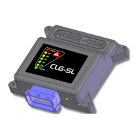
Details the green LED, bargraph, and emergency button box LEDs for status and fault indication.

LED signaling for load thresholds

Describes how red and yellow LEDs indicate load limits exceeding 90% and 100%.

Inputs

Reset and Limit Reduction Inputs

Describes RESET input for temporary override and LIMIT REDUCTION for critical areas.

Transducer and Control Inputs

Covers PRESSURE transducer input (4-20mA) and INPUT DV for remote control.

Setting parameters by final user

Programming with external keyboard

Explains using the optional PRG-CLG keyboard for programming device thresholds.

Hardware key for threshold increase

Details using the PRG2 to temporarily increase the load limit threshold up to 125%.

PC connection for configuration

Outlines scenarios requiring PC connection via serial adapter for parameter management.

Error code

Working state error codes

Summarizes green LED blinking patterns for errors in the working state.

Autotest and emergency state codes

Details LED blinking for autotest errors and emergency button activation.