Installation Instructions Installation Instructions
13
1 Dear user
Congratulations on purchasing your Faber product, a quality
product that will provide you with the warmth and atmosphere for
many years. Please read the user manual before using the re.
Should a malfunction occur despite the careful nal checks, then
you can always contact your Faber dealer.
Please note:
The data of your re is available in the user manual.
1.1 Introduction
Only have the appliance installed by a qualied installer according
to the gas safety regulations.
Read this installation manual properly.
1.2 Please check
Check the re for transport damage and report any damage
immediately to your dealer.
1.3 CE Declaration
Glen Dimplex Benelux certies that this Faber re complies with the
essential requirements of the gas appliances directive.
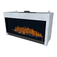
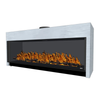
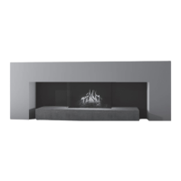
Product: gas room heater
Model: MatriX 800/500-I/IIL/IIR/III
MatriX 800/650-I/IIL/IIR/III
Applicable EC directives: 90/396/EEC
Harmonized standards applied: NEN EN 613:2000 and NEN EN
613/A1:2003
This declaration is invalid, if without the written permission of Glen
Dimplex Benelux:
• Changes are made to the appliance.
• The re is connected to other exhaust materials than
specied.
2 Safety instructions
• The unit must be installed and subsequently serviced every
year and maintained in accordance with these instructions
and the applicable national and local regulations.
• Ensure that the data on the type label matches the local gas
type and pressure.
• The settings and the construction of the re must not be
changed!
• Do not place extra imitation wood or other smoldering
material on the burner or in the combustion chamber.
• The appliance is for atmosphere and heating purposes. This
means that all surfaces, including the glass, can be very hot
(over 100°C). Exceptions to this are the bottom of the re
and the control elements.
• Do not place any combustible materials within 0,5m of the
radiation area of the re.
• Through the natural air circulation of the re moisture and
uncured volatile components from paint, building materials
and carpeted oors, etc. are attracted. These parts can settle
as soot on cold surfaces. Therefore do not light the re
shortly after installation.
• Light the re for the rst time and run for several hours on the
highest setting, so that the paint can cure. Provide adequate
ventilation, so that any fumes can disperse; we recommend
vacating the room during this process.
> Please note:
1. All transport packaging is removed.
2. No children and pets in the room present.
3 Installation requirements
3.1 Fire
• This device can be built into an existing or new chimney.
• For devices with exible gas pipes, the gas regulator block is
mounted on the right side of the re for transport reason (g
1.6). The gas regulator block with the receiver and the I.T.C.
must be placed on a distance of max. 30cm behind a service
door.
When desired, there are 2 metres burner pipes
(To prevent damage to cables and pipes during transport,
these are tied together with tie-wraps.
Remove it to ensure the proper functioning of the appliance).
3.2 False chimney breast or other structure
• The false chimney should be of non-combustible material.
• The space above the re should always be ventilated using
the supplied grids or a similar alternative with minimal free
passage of 200cm² per grid.
• The false chimney breast and its construction may not rest on
the appliance.
• It is not permitted to start directly on the device with
concentric cut down pipe material.
The air supply could then possibly be closed.
3.3 Flue pipe and terminal requirements
• For the supply of the combustion air and the discharge of the
combustion gases you should always use the Flue materials
specied by Faber. Only when using these materials can
Faber guarantee the safe and proper operation of the
appliance.
• The outside of the concentric ue material can heat up to
+/-150°C. Ensure, when penetrating a ammable wall or
ceiling, construction with proper insulation and protection.
And ensure respective distance.
• Ensure for great discharge lengths that the concentric
discharge material is supported every 2m, so that the weight
of the material is not supported by the re.
• It is not permitted to start directly on the device with
concentric cut down pipe material.
The air supply could then possibly be closed.
 Loading...