Installation Instructions Installation Instructions
14
3.4 Terminals
The combined supply and discharge can be done both via wall or
through the roof or through an existing chimney. Verify if the
position of the terminal meets the local regulations regarding
ventilation openings.
The ue outlet can end on an external wall or a roof. Check
whether the outlet desired by you complies with local requirements
concerning good function and ventilation systems.
> Please note:
For a proper functioning the terminal should be at least 0,5m. away
from:
• Corners of the building
• Roof overhangs and balconies
• Eaves (with the exception of the roof ridge, see Chapter 15)
3.4.1 C11, wall terminal
For a facade or wall outlet use a wall terminal (see g. 1.9 C11).
Depending on the calculation this can be a diameter of
130/200mm or 100/150mm.
3.4.2 C31, roof terminal
For a at or pits roof outlet use a long roof outlet with a diameter of
100/150mm (see g. 1.9 C31).
3.4.3 C91, existing chimney
For an existing chimney use the short chimney outlet with a
diameter of 100/150mm (see g. 1.9 C91).
In this case the existing chimney acts as air inlet an inserted exible
stainless steel pipe discharges the ue gas. The top and the bottom
should be airtight.
Depending on the calculated outlet diameter, use a exible
stainless steel tube of Ø100mm or Ø130mm with CE marking
for 600°C.
> Please note:
The minimum chimney diameter for a 130mm exible stainless
steel pipe must 200x200mm. and for a 100mm exible stainless
steel pipe 150x150mm.
3.5 Existing chimney
You can also connect to an existing replace chimney. The existing
chimney functions then as air supply and a exible stainless steel
tube drawn through the chimney carries the ue gases. The exible
stainless steel tube of Ø100mm must have a CE mark have up to
600°C.
The chimney must have the following conditions:
• The channel of the chimney must be at least 150x150mm.
• There should be no more than one device on a chimney.
• The chimney must be in good condition:
- no leakage
- well cleaned
For more information about connections to existing chimneys, ask
the installation manual “chimney connection set”.
4 Preparation and installation
instructions
4.1 Gas connection
The gas connection must comply with the applicable local
standards.
We advise using a Ø 15mm gas connection directly from the gas
meter to the appliance, with a shut-off valve in the proximity of the
appliance, which must always be freely accessible.
Position the gas connection so that it is easily accessible at all
times for service, and that the burner unit can be disassembled.
4.2 Electrical connection
The power supply must comply with the applicable local standards.
A wall socket 230VAC/50Hz must be installed near the re.
For power supply make use of the included plug adapter.
See g 2.8 or 2.9 for the wiring diagram of this connection and the
LED Symbio module.
A = plug adapter
B = control unit
C = receiver
D = LED Symbio module
E = control block
F = magnet valve
G = 2nd thermocouple
4.2.1 Smart-Home installation
You can connect the control unit to the receiver with an external
source, such as a Domotica home automation system, using the
5-wire pin connector.
(Part G60-ZCE/1000, art.no.: 06022950). The total length of the
cable may not exceed 8m. Signal relay (gold-plated contacts) or
opto-couples are recommended!
4.2.2 Faber ITC (Intelligent Technical Controller)
The ITC gives you more options, such as ECO control, control,
error messages, maintenance advice and such.
For further information see the ”ITC” user manual.
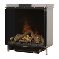
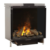
4.3 Preparing the re
• Remove the re from its packaging. Ensure that the gas
supply pipes under the appliance are not damaged.
• Remove frame and glass and take the packaged parts from
the re.
• Store frame and glass in a safe place.
• Prepare the gas connection on the regulator.
4.4 Positioning the re
Take the installation requirements into account (see Chapter 3).
Place the appliance in the right position and set the height with the
(optional) leg levelers.
Height adjustment and levelling of the appliance (see point C, g.
1.1).
Rough height adjustment:
• With the extendable (optional) leg.
Fine adjustment:
• With the adjustable feet.
 Loading...