6
VRTMT8
…12 … 20
… 28
… 40 … 50 … 60
2,5 2,5/4
6 10
Section power cables (mm²)
1,5
(Ls = 9)
(Ls =12) (Ls = 15)
16 16/25
Section control cables (mm²) 0,2÷1,5 (Ls = 9)
Line fuses (A) 10/16 16/20
25 35 50 63 80
Extrarapid fuses (A) 16 25 32 50 63 80 100
I²t (A²S) max energy c.c. 610 720 720 8000 15000 15000
80000
Ls = electrical wire peeling length (mm)
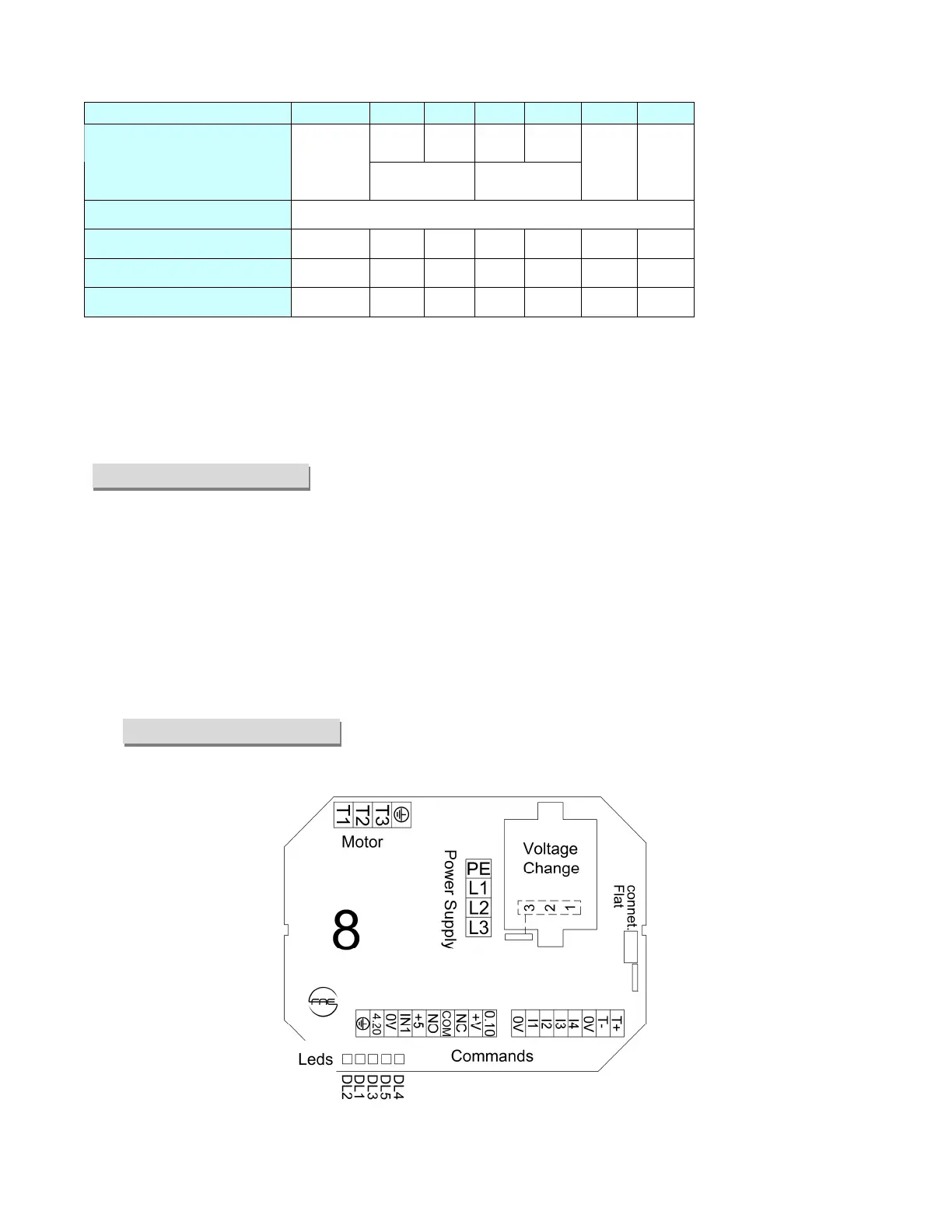
To connect wiring to the spring terminals, apply leverage with a screwdriver on the lever or on the rectangular hole
to open the terminal (see below the panoramic view cards). The power wires of the VRTMS50 and 60 regulators
must be crimped to form an eyelet (M6 hole) and the nuts (E10) tightened with a wrench.
LED WARNING SIGNALS
DL1 : yellow, starts to flash with input signal at
minimum and increases the flashing frequency as
the signal rises. It goes on steady with signal =
100%. It follows the priority signal (see Basic Sett.
[BS] in the Factory Parameters menu).
DL2 : green, steady ON = power supply ON.
DL3 : red, warning alarm ON:
1 flash = power phase lost.
2 flashes = external emergency.
3 flashes = internal over-temperature.
4 flashes = probe missing.
5 flashes = stop for parameters programming or
error settings.
DL4 : green, flashing in modbus transmission.
DL5 : red, flashing in modbus reception.
PANORAMIC VIEW CARDS