Drives
3.
180
Ref.1912
DDS
HARDWARE
· 118 ·
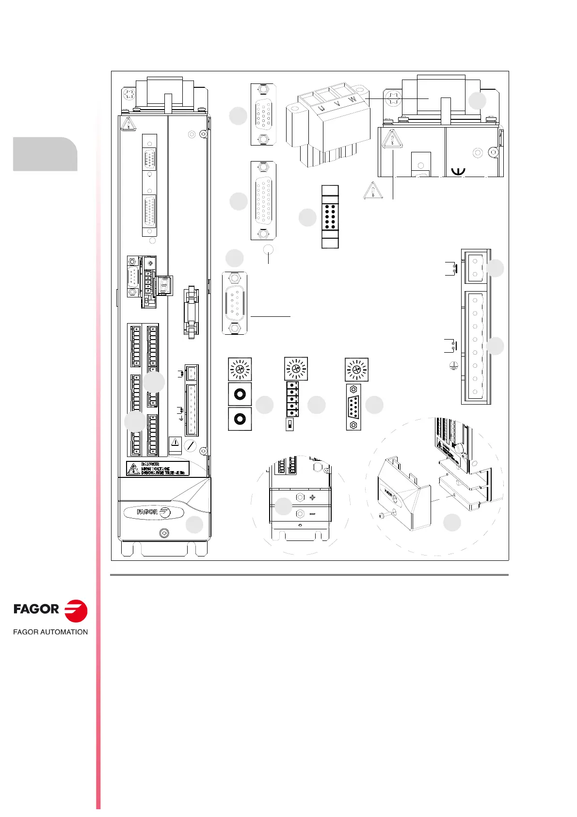
MMC 1.35
These drives have the following connectors:
F. H3/54
MMC 1.35 modular drive. Connectors.
1. Power connector for motor connection.
2. Power DC BUS that feeds the drives from the power supply through metal plates.
X1. Connector that may be used to establish communication between modules through the internal bus.
X2. Connector for the basic control signals.
X3. Connector with two possible uses:
• as output of the encoder simulator.
• as input of the direct feedback for the position loop.
X4. Connector for motor feedback connection (encoder).
X5. Connector for RS-232 serial line connection.
X6. Possible connectors that may be located in this position:
• SERCOS-II
a
or CAN
b
interface connector (always with X5).
• Connector for RS-232/RS-422
c
serial line connection (never with X5).
X7. Connector for external acknowledgment of the status of the safety relay.
SL1. Slot for the cards A1, 16DI-8DO and 8DI-16DO.
SL2. Slot for the cards 16DI-8DO and 8DI-16DO.
RESET button
WARNING. AC touch current greater than
3.5 mA. Install a ground wire with a section
of at least 10 mm² (Cu) or 16 mm² (Al).
+24Vdc
0 V
SPEED
ENABLE
DRIVE
ENABLE
GND
DR.
O.K.
AS1
AS2
CANSERCOS RS422
(a) (b) (c)
NODE
SELECT
NODE
SELECT
0
1
0
4
8
4
0
8
0
4
8
1
2
3
4
5
1
9
NODE
SELECT
OUT
IN
X4
X3
X1
X5
SL2
SL1
+24Vdc
0V
SPEED
ENABLE
DRIVE
ENABLE
GND
X7
X2
UVW
STATUS
DISPLAY
X6
positioning drive
2.5A(F)
FUSE
(250V)
DR.
O.K.
AS1
AS2
Possibilities:
X5. Serial line RS-232 + (X6.SERCOS
a
or X6.CAN
b
)
or X6. Serial line RS-232/RS-422
c
·without X5·
BOOT button.
Software update & SERCOS|CAN
transmission speed selection.
2
SL1
SL2
 Loading...