Auxiliary modules
AUXILIARY MODULES
External Ballast resistors
4.
Ref.1912
· 187 ·
DDS
HARDWARE
Chapter 8. INSTALLATION shows the installation rules for external braking
resistors that must be followed strictly in order to install them properly.
Chapter 11. DIMENSIONS of this manual shows their dimensions.
Outside look
The independent resistors whose model is ER+TH-18/+FAN are external
electrical resistors that can also be used with power supplies and compact
drives that have an internal thermostat and a single-phase 220 V AC cooling
fan.
T. H4/7 External Ballast resistor with internal thermostat. Technical data.
With internal thermostat ER+TH-18/1800 ER+TH-18/2200
Resistor 18 18
Tolerance ±5 % ±5 %
RMS power 1.3 kW 2.0 kW
Energy absorbed in 5"
overloaded
55 kJ 83 kJ
Operating room temperature 5°C/45°C (41°F/113°F)
Storage temperature -20°C/60°C (-4°F/140°F)
Relative humidity < 90 % non condensing at 45°C/113°F
Operating vibration 0.5 g
Shipping vibration 2 g
Sealing IP 54 IP 54
Approx. mass kg/lb 3.0/6.61 7.0/15.43
Note that the value for the RMS power depends on the following conditions:
Resistor installed vertically with the connection cables at the bottom and separated
from the nearest surface at a distance of at least 10 cm (about 4 in).
WARNING. HEAT DANGER. DO NOT TOUCH the surface of these
resistors. Remember that it may reach temperatures around 410°C/770°F.
If it is installed to be easily accessible, precautions must be taken to prevent
unintentional contact. Also avoid heat sensitive items (cables, etc.) from
coming into contact with the surface to avoid damaging or destroying these
elements and/or causing other more dangerous situations.
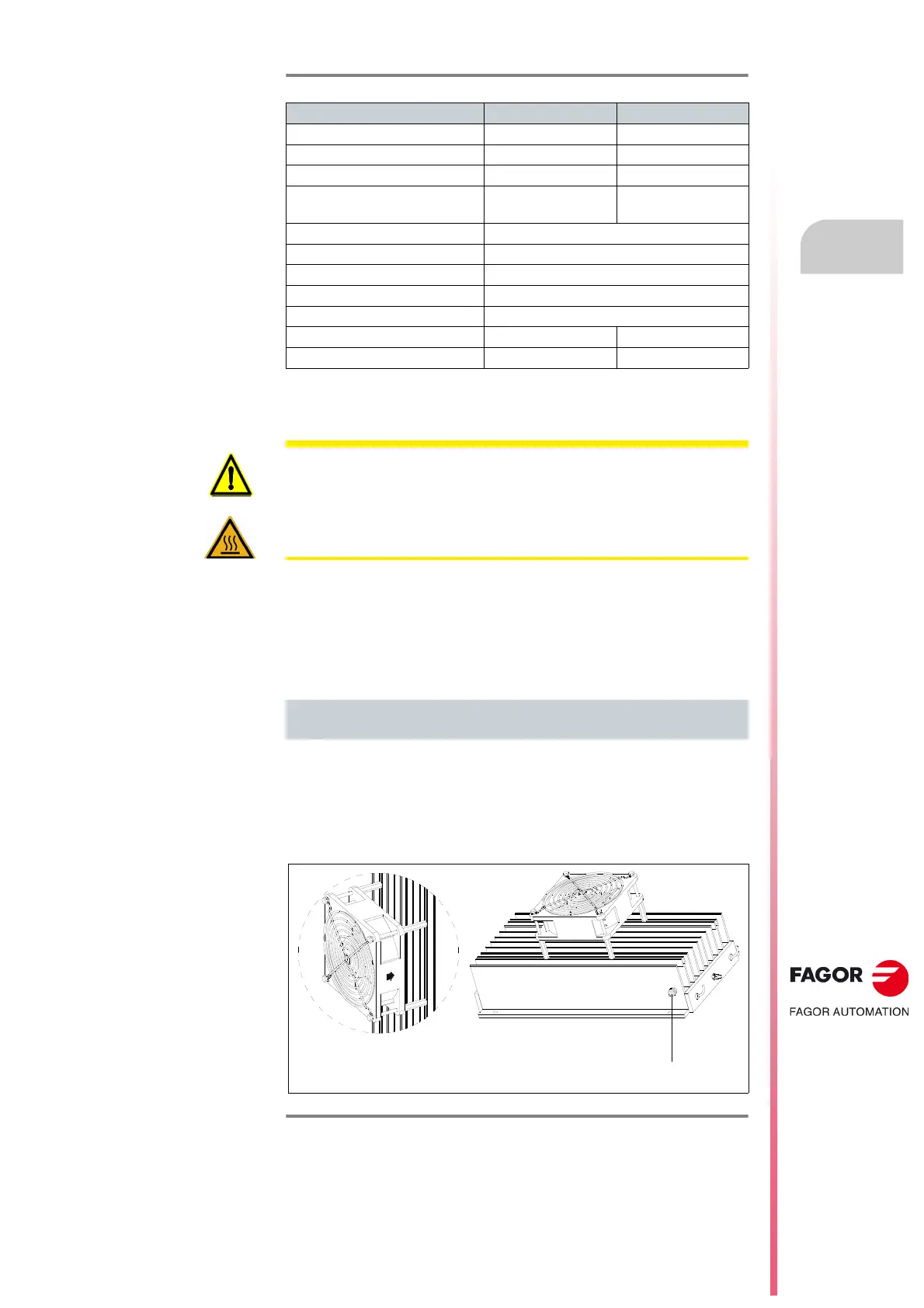
ER+TH-18/x+FAN
resistor with internal thermostat and fan
F. H4/5
External Ballast resistor with internal thermostat and a fan. Outside look.
Temperature sensor
ER+TH-18/1000+FAN
ER+TH-18/1500+FAN
ER+TH-18/2000+FAN
 Loading...