Auxiliary modules
AUXILIARY MODULES
Bus protection module. BPM
4.
Ref.1912
· 199 ·
DDS
HARDWARE
FAGOR supplies the aerial connector in the accessory bag. The values for
pitch, tightening torque, pole section (input holes of the connector) and other
data regarding the terminals of this connectors are shown in the following
table.
Chapter 8. INSTALLATION describes the procedure for a correct installation
of the braking resistors to the BPM through this connector and of the unit in
the system.
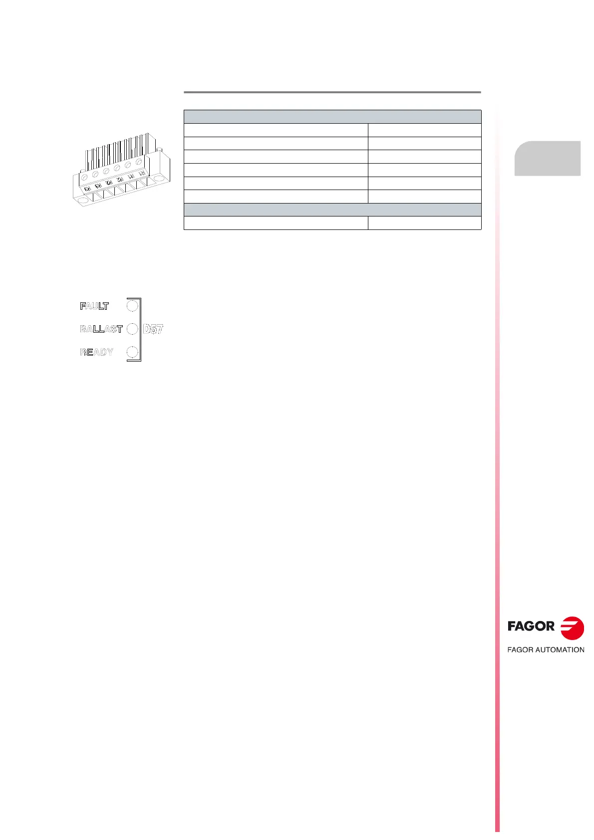
D57, status light indicators
FAULT. There is an error. Top LED red.
BALLAST. Crowbar activated. Middle LED amber.
READY. Unit ready. Bottom LED green.
T. H4/16 Aerial connector that may be plugged into X56. Technical data.
Connector data
Nr of poles 6
Gap (mm) 7.62
Min./max. tightening torque (N·m) 0.5/0.6
Screw thread M3
Min./max. section (mm²) 0.2/4
Rated current In (A) 20
Wire data
Length to strip (mm) 7
 Loading...