Installation
8.
Ref.1912
· 277 ·
DDS
HARDWARE
Connection diagrams
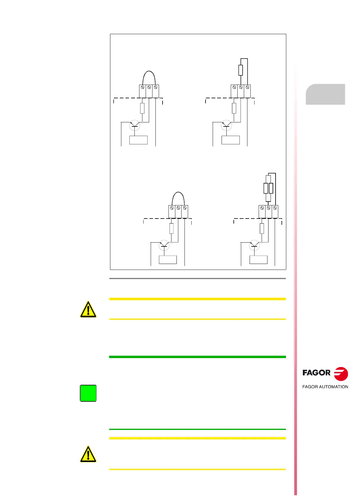
How to configure this connection on compact drives
Internal or external resistor?
F. H8/12
Configuration of the electrical connection of the Ballast resistor in power
supplies.
C
ONTROL
L-
L+
R. int
R. ext
2x ER+TH-18/X
PS-65A
XPS-65
L+
Re
Ri
R. int
L+ReRi
C
ONTROL
2x ER+TH-18/X+FAN
PS-65A
XPS-65
L-
L+
Configuration
for connecting the
internal
Ballast resistor
Configuration
for connecting the
external
Ballast resistor
C
ONTROL
L-
L+
R. int
Configuration
for connecting the
internal
Ballast resistor
R. ext
ER+TH-18/X
PS-25B4
XPS-25
L+
Re
Ri
R. int
L+ReRi
C
ONTROL
ER+TH-18/X+FAN
PS-25B4
XPS-25
L-
L+
Configuration
for connecting the
external
Ballast resistor
WARNING. Never connect an external resistor in parallel with the internal
Ballast resistor. It may cause severe damage to the system.
INFORMATION.
Compact modules ACD/SCD/CMC 1.08/1.15 have an internal Ballast
resistor. If necessary, an external resistor may be connected instead of an
internal. See the electrical configuration in the diagrams of the figure and read
the warning below.
Compact modules ACD/SCD/CMC 1.25/2.35/2.50 and SCD 2.75 do not have
an internal Ballast resistor. FAGOR supplies an external Ballast resistor
associated with each one of these modules as an accessory with the unit.
Always connect according to configuration (L+, Re). See the electrical
configuration in the diagrams of the figure.
WARNING. When connecting an external braking resistor (Ballast) on
ACD/SCD/CMC 1.08/1.15 modules, make sure that its Ohm value is exactly
the same as that of its internal Ballast resistor. See table
T. H3/18 which
indicates this value.
 Loading...