Connection diagrams
10.
Ref.1912
· 357 ·
DDS
HARDWARE
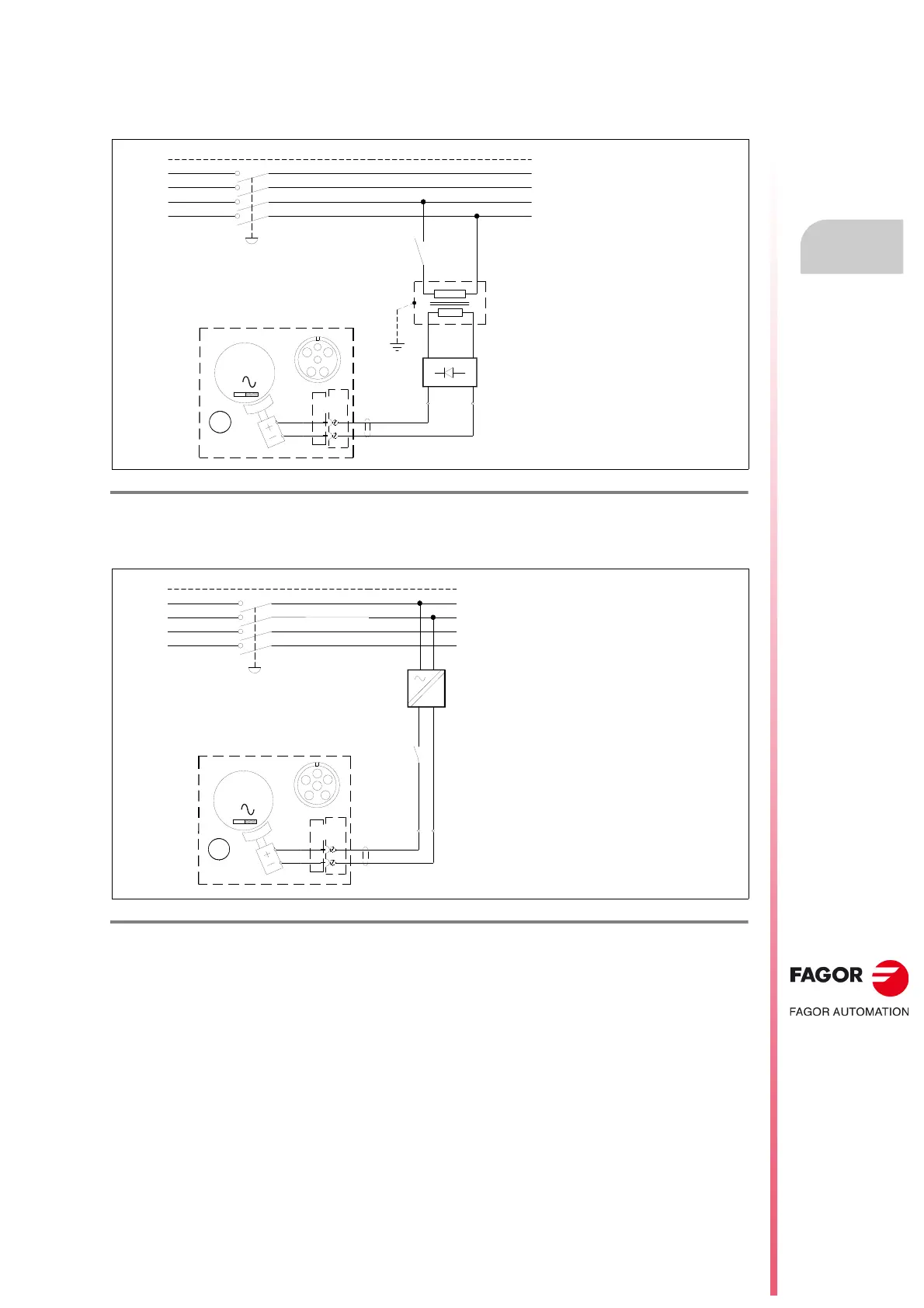
10.17 Holding brake connection diagram
FXM synchronous motor
FKM synchronous motor
F. H10/3 1
Connection diagram for the holding brake of an FXM synchronous servo motor.
F. H10/3 2
Connection diagram for the holding brake of an FKM synchronous servo motor.
PE
3x 400-460 VAC
L1
FXM MOTOR
BRAKE
E
F
+24 VDC
0 VDC
BR
24 VAC
230 VAC
E
F
3
M
Z
- S1
MECHANICAL MAIN SWITCH
SIMPLE CIRCUIT TO POWER
THE FXM MOTOR BRAKE
POWER MAINS
(R)
(S)
(T)
L2
L3
N
FKM MOTOR
BRAKE
4
5
+24 VDC
0 VDC
BR
3
M
Z
4
5
+24 V
=
400 VAC
0 V
PE
3x 400-460 VAC
L1
POWER MAINS
(R)
(S)
(T)
L2
L3
N
- S1
MECHANICAL MAIN SWITCH
Important.
Power the holding brake with a power
supply that provides a continuous, stabilized voltage
of 24 V DC. To ensure safe operation in the event of
large temperature variations, the coil must be
powered with stabilized direct current.
 Loading...