Power supplies
2.
Ref.1912
· 45 ·
DDS
HARDWARE
Terminal strip to connect the Ballast resistor
The power supply is supplied from factory with a wire jumper between
terminals Ri and L+. This configuration of the power supply means that it
comes from the factory with its internal Ballast resistor.
However, if with this internal resistor it is not possible to dissipate enough
power (e.g. when braking), the configuration must be modified so the power
supply can work with an external ballast resistor capable of dissipating that
energy. Remove the wire between terminals Ri and L+ and connect the
proper external resistor between terminals Re and L+. See the diagram in
the figure.
Removing the jumper between Ri and L+ and not connecting an external
ballast resistor generates error code
E215 or E304 on the display. On PS-
25B4 power supplies, the power DC BUS will not be charged.
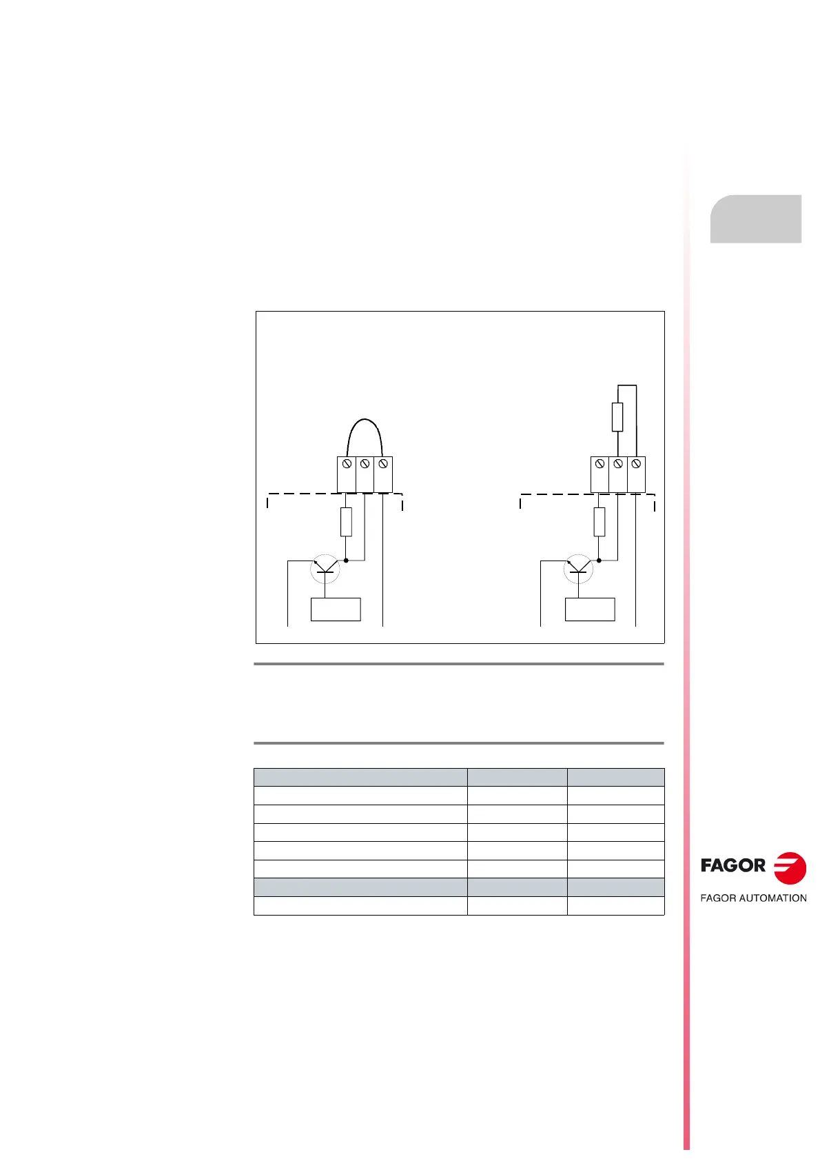
Here is a graphic representation of the two possible configurations:
The following table shows the values for gap, tightening torque (wire entry
holes) and other data regarding the screw-on terminals of the ballast resistor
according to power supply model:
These power supply carry a protection against over-temperature which
triggers error code
E301 on the display and stops its operation when
reaching 105°C/221°F.
F. H2/9
Ballast resistor connection configurations.
T. H2/9 Connection terminals of the ballast resistor. Technical data.
Connector data PS-25B4 PS-65A
Gap (mm) 10.16 -
Min./max. tightening torque (N·m) 1.2/1.5 2/2.3
Screw thread M4 M5
Min./max. section (mm²) 0.5/16 0.5/25
Rated current In (A) 76 76
Wire data
Length to strip (mm) 10 16
Configuration for connecting the
external Ballast resistor
Configuration for connecting the
internal Ballast resistor
L-
L+
L-
L+
PS-25B4
PS-65A
PS-65A
PS-25B4
CONTROL
Ri Re L+ Ri Re L+
CONTROL
R.int
R.int
R.ext
ER+TH-X/X
ER+TH-18/X+FAN