UNLESS OTHERWISE STATED, PAR
NOT TO BE ADJUSTED BY THE
Please ensure that any plastic coatings
to use. Before operation, pan requires
cleaned and dried.
Discolouration of heated parts is
testing to ensure a satisfactory unit.
quality or performance.
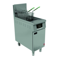
1.1 MODEL NUMBERS, NETT
and DIMENSIONS
Model
Width
(mm)
Depth
(mm)
G401F Fryer
400
840
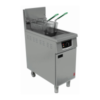
G402F Fryer
400
840
Pan oil capacity:
18 litres cold, good quality oil (to -
1.2 SITING
The unit must be installed on a firm,
lit draught free position. The fryer
in a position where the possibility of
likely when force is applied. The
be the manner of installation, such
a battery of appliances or installing the
or by separate means, such
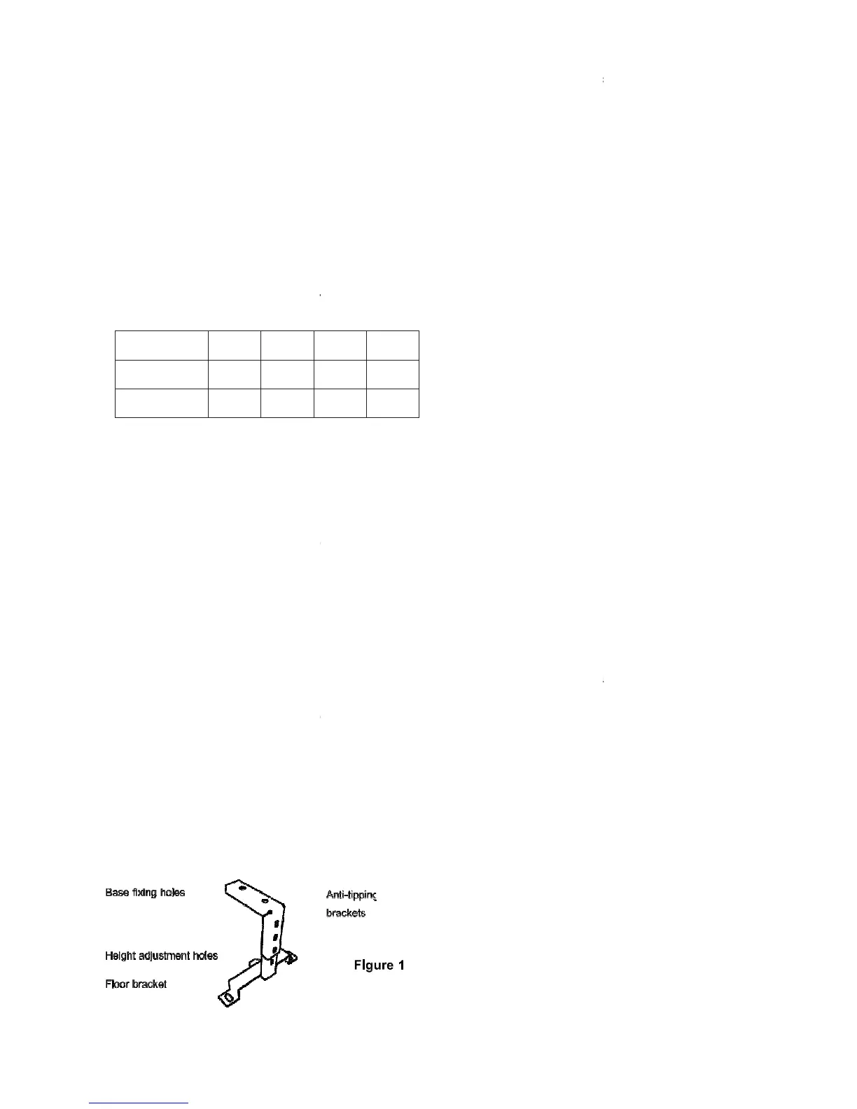
1.2.1 Anti-tipping Accessory
An anti-tipping mechanism is also
accessory. If these are to be fitted, the
fitted to locate the fryer in the correct
any walls as detailed below. Fixing
the fryer base to accommodate the
should be fitted as detailed in Figure
chain has a quick release eyelet.
and secure bracket to floor after
anti-tipping device attached to the
below floor bracket.
Figure 1 - Anti-tipping
Height
(mm)
Weight
(kg)
1200
94
1200
94
1.2.2 Clearances
The unit requires a
Important
If fryer is to be installed
wall or overlying surface.
Some appliances require
determine overall distance
adjoining appliances.
1.3 VENTILATION
The appliance ventilation
should be installed under a
harmful to health.
For multiple installations,
together. Installations should
A competent engineer must
work.
1.4 GAS SUPPLY (Both
The SIT gas valve, situated
governor. The inlet pressure
should be set at test nipple
Page 4 (for either natural
of at least 150mm to rear
other appliances then the
vertically from top of unit.
or outside air. The fryer
natural or mechanical must
be made in accordance with
be used for any installation
gas conversion or repair.
at rear RH side of unit and
should be checked at valve
 Loading...