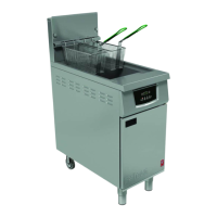
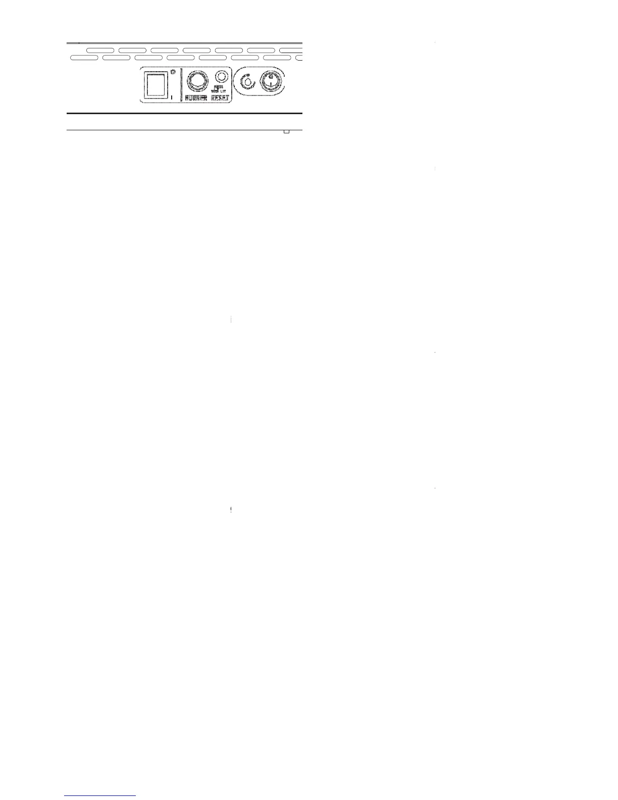
Figure 4 – G401F & G402F -
3.
Burner Lock-Out Reset Switch
Resets burner for further lighting
lockout indicator is illuminated.
4.
Filtration Pump Switch
Energises filtration pump when
OFF (O) position.
5.
Temperature Safety Limiter Reset
Inside red recess.
2.4.4 G401F Controller Diagnostic
On printed circuit board of controller,
behind control panel)
Green LED ‘ON’ indicates heat
Green LED ‘OFF’ indicates no heat
Red LED flashes if temperature probe
open circuited.
Red LED is permanently ‘ON’ to
Set point is +/-7⁰C of mid-set point.
2.5 PRE-COMMISSIONING CHECK
1.
Clean out pan thoroughly using
detergent. Rinse out and dry
Note
For further detail with regard to
Section 8.
2.
Ensure drain valve is closed. Fill
indicated on basket hanging rail.
Note: MAX refers to maximum hot
3.
With gas supply still shut off, turn
supply.
4.
Open door and press
reset button (red), refer to
switch to Position 'I' (ON position).
5.
Turn control knob to desired
illuminate (Figure 2, item 4).
4
6.
G402F is factory preset
7.
Fryer ignition sequence
14 seconds after completion
On printed circuit board of controller,
system is OK.
hot water and
indicator will
detected during first attempt.
2nd attempt).
8.
The neon next to
9.
Turn gas supply on.
10.
Press lockout reset
indicator will extinguish).
11.
Burner will ignite and
signify that burner is on.
bled from supply and burner
2.5.1 Checking Controller
Controller - Section 6.2.3.
2.5.2 Checking Oil
Important
After installation, the
for gas leaks and ensure the
and satisfactorily before
The unit is equipped with an
thermostat, independent of
temperature to rise above
zone (230
⁰
C), limit device
controller. It will also stop
To re-set temperature limit
to OFF position.
b) Allow oil to cool below
similar item. The button is
of first attempt if no flame is
(Unit will only lock out after
indicator will illuminate to
Steps 10 -11 until air is
additional temperature limit
activate and cut power to
located behind cabinet door
 Loading...