2.2 Connect the AT(M)
Before connecting, turn off the power and turn it back on only after the entire installation is ready.
If an end station controls more than one AT(M) unit (max. 3) in a parallel circuit, each AT(M) unit
must be wired directly from the end station. Do not wire from a connection box of one AT(M) unit to a
connection box of another AT(M) unit.
Make sure that the AT(M) is well and properly grounded according to the guidelines.
Keep signal and power cables as short as possible. If the length of the cable is longer than 40m, the
0V wire of the 24Vac power supply has to be connected double. Do this for all AT(M) units which are
connected to the same end station. The cable length may never exceed 100m.
The voltage and frequency data on the actuator identification plate must correspond to the power
supply.
Place cables preferably in a duct (separate signal cables from power supply cables).
Use low current cables for the electrical connection of the AT(M).
Connect the AT(M). Use the:
● Technical specifications (see (p. 5)).
The voltage and frequency data on the actuator identification plate must correspond to the power
supply.
● Connection diagram (see (p. 6)).
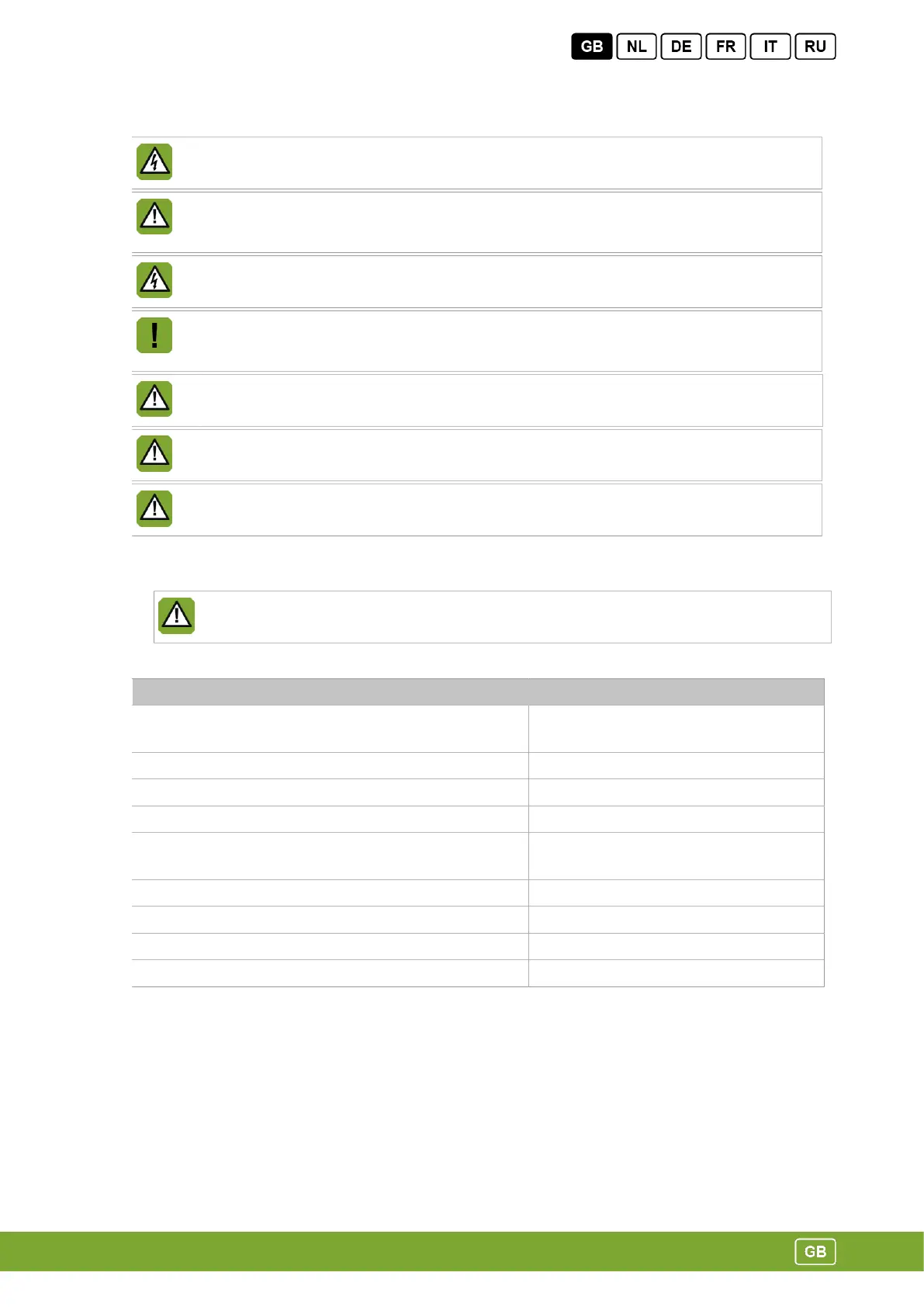
AT Control damper
Supply voltage 18-24Vac + 10% (ATM 35-56)
24Vac + 10% (ATM 63-80)
Power consumption 4W
Max. current 200mA
Control signal 10-0Vdc
Running time 90° angular rotation 22 sec. (ATM 35-56)
49 sec. (ATM 63-80)
Normal condition at delivery 0Vdc open, 8.5Vdc almost closed
Possibility to adjust the position at maximum control voltage
Transformer max. 16 actuators on 100VA transformer
PFB (Power Fail Box) max. 16 actuators on PFB
5